Pfaff 1245 - 1246 Owner's Manual - Page 58
djustmen
 |
View all Pfaff 1245 - 1246 manuals
Add to My Manuals
Save this manual to your list of manuals |
Page 58 highlights
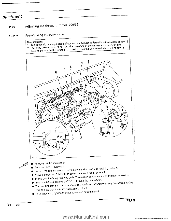
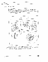
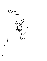
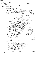
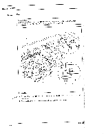
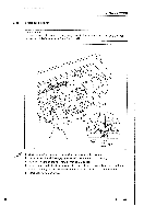
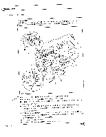
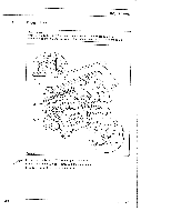
djustmen t 11.05 11 0501 Adjusting the thread trimmer -900/56 Pre-adjusting the control cam R21.. eTbWqheeauitrhieincetgchneesnutttrarfikacec-beuep(ainrlientvhgee-rsduaitrrfeiatcscteiToDonfCoc,fotnrhotetraobtlieocgnai>nmnmi5nugsmtoubfsetthbueenldaleartrgenereasatlltyehcictnhetenhtepriocmiintiytddoolffeptohawfe>pa8w. l 8. 11 - 20 11 .17 • Remove catch 1 (screws 2). • RLMITBnoeuromoitrnhvnsgoieescvntcoehponteohnptsrteltioraatolitfkoleoecnuc-a3urambp(msrscic5nlre5rgeveinwlweraertstshettareoo4iafn>ldi.litcynisorgeinTnctDctraoioCoclllncabcoryoar7fmdtuartroon5ntcairaentenigsowdtntishotchinenrerchaewoacqnncsutodr6irowrdleohamfcenaercemele.ntatw5in1iait.nhngdrcetioqglulhaitrree7nm. secnretw2,s care to In this note that it is touching retaining position, tighten the four screws collar 7. on control cam 5. 6. taking PFAFf
-
 1
1 -
2
-
3
-
4
-
5
-
6
-
7
-
8
-
9
-
10
-
11
-
12
-
13
-
14
-
15
-
16
-
17
-
18
-
19
-
20
-
21
-
22
-
23
-
24
-
25
-
26
-
27
-
28
-
29
-
30
-
31
-
32
-
33
-
34
-
35
-
36
-
37
-
38
-
39
-
40
-
41
-
42
-
43
-
44
-
45
-
46
-
47
-
48
-
49
-
50
-
51
-
52
-
 53
53 -
 54
54 -
 55
55 -
 56
56 -
 57
57 -
 58
58 -
 59
59 -
 60
60 -
 61
61 -
 62
62 -
 63
63 -
64
-
65
-
66
-
67
-
68
-
69
-
70
-
71
-
72
-
73
-
74
-
75
-
76
-
77
-
78
 |
 |