Pfaff 1245 - 1246 Owner's Manual - Page 62
C61AO
 |
View all Pfaff 1245 - 1246 manuals
Add to My Manuals
Save this manual to your list of manuals |
Page 62 highlights
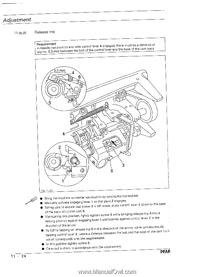
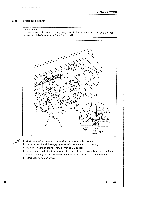
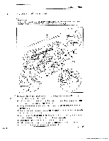
Adjustment 11.05.05 Release trip RaInpepnqreouexidr.ele0m.3reisnmet mposbietitowneaenndtwheithboclot notfrothl elecvoenrt4roel nlgevaegredan, dthtehree must be a base of the distance of cam track. 6 11-24 \ -\ ((C(61AO iA'\ I \3 1 Fig. 11 -21 • • • Bring the machine to needle rise Manually activate engaging lever Taking care to ensure that screw position by turning the handwheel. 1 so that pawl 2 engages. 3 is still loose, press control lever 4 down to the base • of the track of control cam 5. Maintaining this position, lightly tighten resting position against engaging lever screw 3 while bringing release trip 1 and laterally against control lever 6 2 into a in the • direction of the arrow. By lightly tapping on release trip tapping control lever 4, create a 6 in the direction of the arrow, distance between the bolt and while simultaneously the base of the cam trac which corresponds with the requirement. • In this position tighten screw 3. • Carrq out a check in accordance with the requirement. PFAFI
-
 1
1 -
2
-
3
-
4
-
5
-
6
-
7
-
8
-
9
-
10
-
11
-
12
-
13
-
14
-
15
-
16
-
17
-
18
-
19
-
20
-
21
-
22
-
23
-
24
-
25
-
26
-
27
-
28
-
29
-
30
-
31
-
32
-
33
-
34
-
35
-
36
-
37
-
38
-
39
-
40
-
41
-
42
-
43
-
44
-
45
-
46
-
47
-
48
-
49
-
50
-
51
-
52
-
53
-
54
-
55
-
56
-
 57
57 -
 58
58 -
 59
59 -
 60
60 -
 61
61 -
 62
62 -
 63
63 -
 64
64 -
 65
65 -
 66
66 -
 67
67 -
68
-
69
-
70
-
71
-
72
-
73
-
74
-
75
-
76
-
77
-
78
 |
 |