Pfaff 1245 - 1246 Owner's Manual - Page 74
Tension, release
 |
View all Pfaff 1245 - 1246 manuals
Add to My Manuals
Save this manual to your list of manuals |
Page 74 highlights
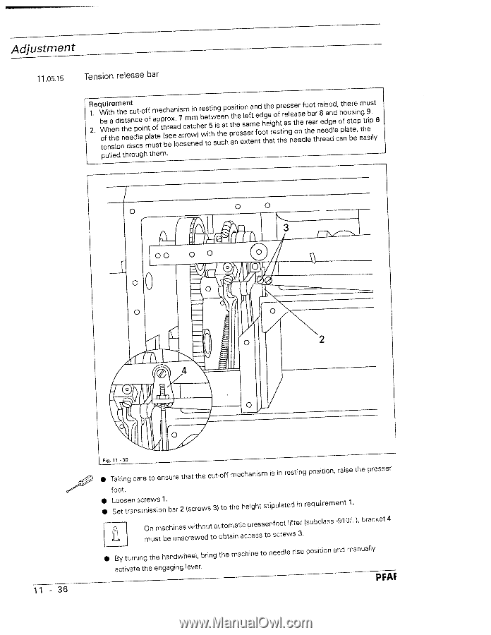
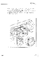
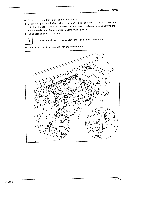
Adjustment 11.0515 Tension release bar R12..eqWbWotueefinihttrahsheeinedmothintsneehtendaeectinduspcctloe-esoinofpmftflauomatfspeetptch(brshoreeeaxeanl.odia7sormcrsmaoetwnmicne)hdrebweretsiottt5hiwnsigeusthecaepnhtoptasthhrinteeeisoeslsxneaetfmeartnnfeedtodohtgthteheaiergteohpstfhttrireenaessglnseteeaohersnedeftlorhebeoeaattrrhnrr8aeeeideaasgdenddlede,coahtpfnholaseubttrseoeei,npemgthatrsue9iip.slyt6 pulled through them. 11 - 36 Fig. 11 3O • Taking care to ensure that the cut-off mechanism is in resting position, raise the presser foot. • • Loosen screws 1 Set transmission bar 2 (screws 3) to the height stipulated in requirement 1. Omnusmt abcehiunnesscwreiwtheoduttoauotbotmaiantiaccpcreessssetor-fsocoretwlifste3r. (subclass -910/..), bracket 4 • By turning the handwheel, bring the machine to needle rise position and manually activate the engaging lever. PFAF
-
 1
1 -
2
-
3
-
4
-
5
-
6
-
7
-
8
-
9
-
10
-
11
-
12
-
13
-
14
-
15
-
16
-
17
-
18
-
19
-
20
-
21
-
22
-
23
-
24
-
25
-
26
-
27
-
28
-
29
-
30
-
31
-
32
-
33
-
34
-
35
-
36
-
37
-
38
-
39
-
40
-
41
-
42
-
43
-
44
-
45
-
46
-
47
-
48
-
49
-
50
-
51
-
52
-
53
-
54
-
55
-
56
-
57
-
58
-
59
-
60
-
61
-
62
-
63
-
64
-
65
-
66
-
67
-
68
-
 69
69 -
 70
70 -
 71
71 -
 72
72 -
 73
73 -
 74
74 -
 75
75 -
 76
76 -
 77
77 -
 78
78
 |
 |