Pfaff 1245 - 1246 Owner's Manual - Page 72
Bobbin-thread, clamp, spring, Model, these, adjustments, springs.
 |
View all Pfaff 1245 - 1246 manuals
Add to My Manuals
Save this manual to your list of manuals |
Page 72 highlights
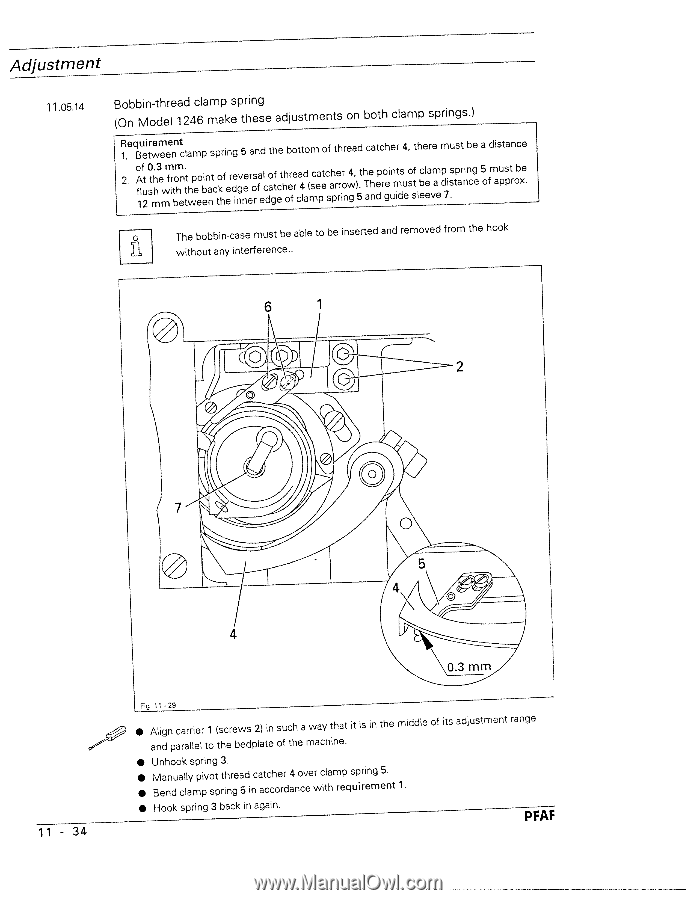
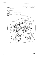
Adjustment 11.05.14 Bobbin-thread clamp spring (On Model 1246 make these adjustments on both clamp springs.) Requirement 1. Between clamp spring S and the bottom of thread catcher 4, there must be a distance 2. oAf1lf2ut 0stmhh.3emwmfirtbmohen.tttwhpeeoebinnatctkohfeerdeignvneeerosrafelcdoagftecthhoerferca4lda(msceapetcsahprerrironwg4,)5.thTaenhdeprogeiunmitdsueosstflbceleeavmaepd7i.ssptarnincge 5 must be of approx. The bobbin-case must be able to be inserted and removed from the hook without any interference.. 6 1 11 - 34 Fig. 11 '29 • Align carrier 1 (screws 2) in such a way that it is in the middle of its adjustment range and parallel to the bedplate of the machine. • Unhook spring 3, • • Manually pivot thread catcher 4 over clamp spring 5. Bend clamp spring 5 in accordance with requirement 1 • Hook spring 3 back in again. PFAF
-
 1
1 -
2
-
3
-
4
-
5
-
6
-
7
-
8
-
9
-
10
-
11
-
12
-
13
-
14
-
15
-
16
-
17
-
18
-
19
-
20
-
21
-
22
-
23
-
24
-
25
-
26
-
27
-
28
-
29
-
30
-
31
-
32
-
33
-
34
-
35
-
36
-
37
-
38
-
39
-
40
-
41
-
42
-
43
-
44
-
45
-
46
-
47
-
48
-
49
-
50
-
51
-
52
-
53
-
54
-
55
-
56
-
57
-
58
-
59
-
60
-
61
-
62
-
63
-
64
-
65
-
66
-
 67
67 -
 68
68 -
 69
69 -
 70
70 -
 71
71 -
 72
72 -
 73
73 -
 74
74 -
 75
75 -
 76
76 -
 77
77 -
78
 |
 |