Pioneer PRO-1010HD Owner's Manual - Page 23
Connecting Control Cords - user manual
 |
View all Pioneer PRO-1010HD manuals
Add to My Manuals
Save this manual to your list of manuals |
Page 23 highlights
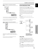
English Audio connection for component connected to INPUT5 INPUT5 AUDIO R L The audio line for the component connected to INPUT5 can be connected to the AUDIO R/L (INPUT5) pin jacks. Sound is output from the SPEAKER (L/R) terminals according to the video input selection. Audio connection for component connected to INPUT3 or INPUT4 INPUT 3/4 AUDIO R L Installation and Connections Connecting Control Cords Connect control cords between this unit and other PIONEER equipment having the Î logo. You can then operate the connected equipment by sending commands from its remote control unit to the remote control sensor on this unit. After the CONTROL IN terminals have been connected, the remote control sensors on the connected equipment do not accept commands from the remote control units. Face the remote control units to the remote control sensor on this unit when operating the connected equipment. Notes ÷ Make sure that the power is turned off when making connections. ÷ Complete all component connections before making control cord connections. CONTROL IN SR OUT OUT CONTROL CONTROL IN SR OUT Installation and Connections CONTROL IN SR OUT Audio input to the AUDIO R/L (INPUT3/4) pin jacks is possible for a component connected to either INPUT3 or INPUT4. Sound is output from the SPEAKER (L/R) terminals according to the video input selection. The control cables (commercially available) are mono sound cables with mini plugs (no resistance). About SR+ The CONTROL OUT terminal on the rear of this unit supports SR+ that allows linked operations with a PIONEER AV receiver. SR+ presents functions such as the input switch linkage operation function and the DSP surround mode display function. For more information, see the user's manual for the PIONEER AV receiver supporting SR+. Note If you use SR+, be sure to perform SR+ related function settings on your PIONEER AV receiver. When doing this, assign the appropriate setting on the receiver side for INPUT1 to INPUT5 of this unit (because this unit does not feature a built-in tuner, there is no TV function). 19 EN
-
 1
1 -
2
-
3
-
4
-
5
-
6
-
7
-
8
-
9
-
10
-
11
-
12
-
13
-
14
-
15
-
16
-
17
-
 18
18 -
 19
19 -
 20
20 -
 21
21 -
 22
22 -
 23
23 -
 24
24 -
 25
25 -
 26
26 -
 27
27 -
 28
28 -
29
-
30
-
31
-
32
-
33
-
34
-
35
-
36
-
37
-
38
-
39
-
40
-
41
-
42
-
43
-
44
-
45
-
46
-
47
-
48
-
49
-
50
-
51
-
52
-
53
-
54
-
55
-
56
-
57
-
58
-
59
-
60
-
61
-
62
-
63
-
64
-
65
-
66
-
67
-
68
-
69
-
70
-
71
-
72
-
73
-
74
-
75
-
76
-
77
-
78
-
79
-
80
-
81
-
82
-
83
-
84
-
85
-
86
-
87
-
88
-
89
-
90
-
91
-
92
-
93
-
94
-
95
-
96
-
97
-
98
-
99
-
100
-
101
-
102
-
103
-
104
-
105
-
106
-
107
-
108
-
109
-
110
-
111
-
112
-
113
-
114
-
115
-
116
-
117
-
118
-
119
-
120
-
121
-
122
-
123
-
124
-
125
-
126
-
127
-
128
-
129
-
130
-
131
-
132
-
133
-
134
-
135
-
136
-
137
-
138
-
139
-
140
-
141
-
142
-
143
-
144
-
145
-
146
-
147
-
148
-
149
-
150
-
151
-
152
-
153
-
154
-
155
-
156
-
157
-
158
-
159
-
160
-
161
-
162
-
163
-
164
-
165
-
166
-
167
-
168
-
169
-
170
-
171
-
172
-
173
-
174
 |
 |
