Pioneer VSX94TXH Owner's Manual - Page 19
Connecting your equipment, Installing your speaker system - vsx us
 |
UPC - 012562865607
View all Pioneer VSX94TXH manuals
Add to My Manuals
Save this manual to your list of manuals |
Page 19 highlights
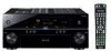
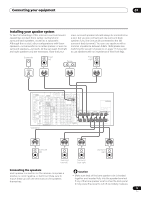
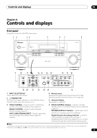
Connecting your equipment 03 Installing your speaker system To take full advantage of the receiver's surround sound capabilities connect front, center, surround and surround back speakers, as well as a subwoofer. Although this is ideal, other configurations with fewer speakers-no subwoofer or no center speaker, or even no surround speakers-will work. At the very least, front left and right speakers only are necessary. Note that your main surround speakers should always be connected as a pair, but you can connect just one surround back speaker if you like (it must be connected to the left surround back terminal). You can use speakers with a nominal impedance between 6 Ω to 16 Ω (please see Switching the speaker impedance on page 74 if you plan to use speakers with an impedance of less than 8 Ω). Subwoofer Front left Center Front right LINE LEVEL INPUT MULTI-ZONE & SOURCE /REC SEL OUT1 ZONE3 OUT2 LAN (10/100) OPTICAL IN 1 (TV/SAT) IN 2 (BD) IN 3 (DVR/ VCR 1) IN 4 (CD-R) 14 ASSIGNABLE IN 1 1 2 (DVD/ LD) IN 2 (CD) COAXIAL IN HDMI IN 1 IN 2 IN 3 IN 1 MAIN IN 2 ZONE2 CONTROL IN OUT IN 1 Y (DVD/ LD) PB MULTI-ZONE & SOURCE IR OUT IN 1 (DVD/LD) IN 2 (BD) ASSIGNABLE 12 OUT Y PB ANTENNA FM UNBAL 75 Ω AM LOOP ZONE2 MULTI-ZONE & SOURCE R ZONE2 L AUDIO PHONO IN CD OUT IN MONITOR MONIOUT TOR OUT DVD/LD IN BD IN TV/SAT IN 1 IN VIDEO / IN 2 GAME 1 IN OUT CD-R/ TAPE/ MD IN R R SUB W. PRE OUT R L FRONT SUB W. CENTER SURROUND R L L FRONT CENTER SURROUND BACK (Single) L SIRIUS IN SPEAKERS IN A FRONT R L PR IN 4 IN 2 Y (BD) PR IN 3 Y OUT DVR/ VCR 1 IN SURROUND R iPod L PB PB OUT OUT DVR/ VCR 2 SURROUND BACK XM PR PR ASSIGNABLE 14 DIGITAL (VIDEO/GAME 1) ASSIGNABLE 1 3 COMPONENT VIDEO S-VIDEO IN VIDEO R L AUDIO 1 2 12 V TRIGGER (DC OUT 12V/ TOTAL 50 mA MAX) RS-232C MULTI CH IN VSX-94TXH CENTER AC OUTLET SWITCHED 100 W(0.8 A) MAX SURROUND R L R SURROUND BACK / B L(Single) SELECTABLE Surround left Surround right Surround back left Surround back right Connecting the speakers Each speaker connection on the receiver comprises a positive (+) and negative (-) terminal. Make sure to match these up with the terminals on the speakers themselves. Caution • Make sure that all the bare speaker wire is twisted together and inserted fully into the speaker terminal. If any of the bare speaker wire touches the back panel it may cause the power to cut off as a safety measure. 19 En
-
 1
1 -
2
-
3
-
4
-
5
-
6
-
7
-
8
-
9
-
10
-
11
-
12
-
13
-
 14
14 -
 15
15 -
 16
16 -
 17
17 -
 18
18 -
 19
19 -
 20
20 -
 21
21 -
 22
22 -
 23
23 -
 24
24 -
25
-
26
-
27
-
28
-
29
-
30
-
31
-
32
-
33
-
34
-
35
-
36
-
37
-
38
-
39
-
40
-
41
-
42
-
43
-
44
-
45
-
46
-
47
-
48
-
49
-
50
-
51
-
52
-
53
-
54
-
55
-
56
-
57
-
58
-
59
-
60
-
61
-
62
-
63
-
64
-
65
-
66
-
67
-
68
-
69
-
70
-
71
-
72
-
73
-
74
-
75
-
76
-
77
-
78
-
79
-
80
-
81
-
82
-
83
-
84
-
85
-
86
-
87
-
88
-
89
-
90
-
91
-
92
-
93
-
94
-
95
-
96
-
97
-
98
-
99
-
100
 |
 |
