Pioneer XDV-P90 Owner's Manual - Page 67
Connecting the Power Cord
 |
View all Pioneer XDV-P90 manuals
Add to My Manuals
Save this manual to your list of manuals |
Page 67 highlights
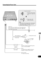
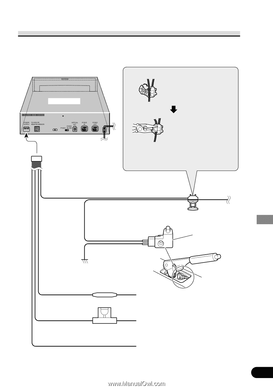
Connecting the Power Cord This Product Connection method 1. Clamp the parking brake switch power supply side lead. 2. Clamp firmly with needle-nosed pliers. Note: • The position of the parking brake switch depends on the vehicle model. For details, consult the vehicle Owner's Manual or dealer. Light green Used to detect the ON/OFF status of the parking brake. This lead must be connected to the power supply side of the parking brake switch. Power supply side Ground side Parking brake switch Installation Fuse resistor Fuse holder Red To electric terminal controlled by ignition switch (12 V DC) ON/OFF. Yellow To terminal always supplied with power regardless of ignition switch position. Black (ground) To vehicle (metal) body. 64
-
 1
1 -
2
-
3
-
4
-
5
-
6
-
7
-
8
-
9
-
10
-
11
-
12
-
13
-
14
-
15
-
16
-
17
-
18
-
19
-
20
-
21
-
22
-
23
-
24
-
25
-
26
-
27
-
28
-
29
-
30
-
31
-
32
-
33
-
34
-
35
-
36
-
37
-
38
-
39
-
40
-
41
-
42
-
43
-
44
-
45
-
46
-
47
-
48
-
49
-
50
-
51
-
52
-
53
-
54
-
55
-
56
-
57
-
58
-
59
-
60
-
61
-
 62
62 -
 63
63 -
 64
64 -
 65
65 -
 66
66 -
 67
67 -
 68
68 -
 69
69 -
 70
70 -
 71
71 -
 72
72 -
73
-
74
-
75
-
76
-
77
-
78
-
79
-
80
-
81
-
82
-
83
-
84
 |
 |
64
Connecting the Power Cord
Installation
Light green
Used to detect the ON/OFF status of the parking brake.
This lead must be connected to the power supply side
of the parking brake switch.
Parking brake switch
Red
To electric terminal controlled by ignition
switch (12 V DC) ON/OFF.
Fuse resistor
Fuse holder
Black (ground)
To vehicle (metal) body.
Power supply side
Ground side
Connection method
2. Clamp firmly with
needle-nosed pliers.
Clamp the parking brake
switch power supply side
lead.
Note:
•
The position of the parking brake switch depends
on the vehicle model. For details, consult the
vehicle Owner
’
s Manual or dealer.
This Product
1.
Yellow
To terminal always supplied with power
regardless of ignition switch position.