ProForm 970 Ci English Manual - Page 10
w/Hole
 |
View all ProForm 970 Ci manuals
Add to My Manuals
Save this manual to your list of manuals |
Page 10 highlights
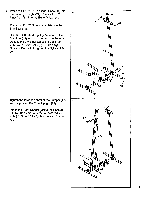
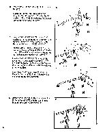
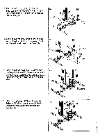
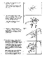
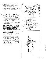
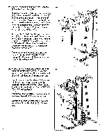
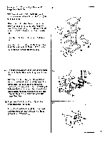
21. Grease the insides of the two 1/2" Bushings (23) in the Frame Top (80). Slide the Press Arm (88) onto the Frame Top (80). Align the two Thick 5/8" Bushings (26) in the Adjuster (61) with the 1/2" Bushings (23) in the Frame Top. Make sure that the Press Arm is turned so the long end of the Adjuster is on the indicated side. Using a rubber mallet, tap the 7 1/2" Axle (30) into the Press Arm, Adjuster and Frame Top. Remove the 10 3/4" Pin (43) from the Press Arm (88) and the Adjuster (61). Remove the Pin Knob (44) from the 10 3/4" Pin. Hold one end of the 10 3/4" Pin against one end of the 7 1/2" Axle (30). Using a rubber mallet, tap the 10 3/4" Pin until the 7 1/2" Axle is centered in the Press Arm. Tighten the Pin Knob (44) back onto the 103/4" Pin (43). Insert the 10 3/4" Pin through the Press Arm (88) and one of the holes in the Adjuster (61). 21 2 80 30 26.E 44 Long 43 End 61 88 22. Press a 2" x 2" Outer Cap w/Hole (28) onto each end of the Press Arm (88). Wet the ends of the Press Arm with soapy water and slide a Small Handgrip (14) onto each end. Find the ends of two Handles (13) that contain inset nuts. Insert those ends of the Handles into one side of the Press Arm (88). Attach each Handle with an 8mm x 3/4" Bolt (6) and 8mm Washer (4). Attach two Handles (13) to the other side of the Press Arm (88) in the same manner. Wet the four Handles (13) with soapy water and slide a Small Handgrip (14) onto each one. 22 13,14 1 88 4 6 13 14 ,11 14 4 28 14 13 1 3
-
 1
1 -
2
-
3
-
4
-
 5
5 -
 6
6 -
 7
7 -
 8
8 -
 9
9 -
 10
10 -
 11
11 -
 12
12 -
 13
13 -
 14
14 -
 15
15 -
16
-
17
-
18
-
19
-
20
-
21
-
22
-
23
-
24
 |
 |
