ProForm 970 Ci English Manual - Page 14
ProForm 970 Ci Manual
 |
View all ProForm 970 Ci manuals
Add to My Manuals
Save this manual to your list of manuals |
Page 14 highlights
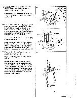
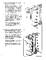
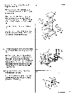
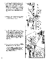
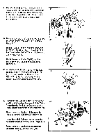
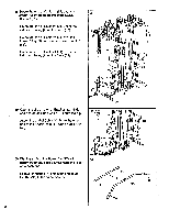
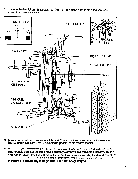
34. Turn the Lock Knob (46) on the side of the Front Upright (72) counterclockwise and pull it outward (see page 21). Insert the Small Backrest Post (34) into the Front Upright and adjust it to the desired position. Release the Lock Knob and turn it clockwise until it stops. Make sure that the pin of the Lock Knob Is in one of the holes in the Small Backrest Post. 35. Attach the Large Backrest (3) to the Butterfly Upright (77) with the two 3/8" x 2 1/2" Bolts (16) and two 3/8" Washers (2). 34 • I .. 46 34 - 72 , I .w e 35 I 11 I ( , , . . ! 77 16 2 -- 36. Find Cable #1 (91). Note: There Is a label attached to one end of each Cable to Identify the Cable. Slide the rubber ball and the two metal washers to the end of the Cable that has an eyelet on it. Lay that end of the Cable over a Pulley (9). Attach the Pulley to the indicated bracket on the Frame Top (80) with a 3/8" x 2" Shank Bolt (8) and 3/8" Nylock Nut (1). lder* 37. Route the other end of Cable #1 (91)'Asimer,me indicated pin on the Press Arm (88). Lay Cable #1 (91) over a Pulley (9). Attach the Pulley to the indicated bracket on the Frame Top (80) with a 3/8" x 2" Shank Bolt (8) and 3/8" Nylock Nut (1). I 36 , - , • ..... 80 \ 91 • - , -c • 9 0000 _ 37 \ . -1-.• ._ ---'' 41 il la P 1 I r'- 0 I Yagli V A 10. ..--' . -c . . .9.. . Pin .":i....:. a .9 1 I 7 :1,1 0.• ll • 9 •III. •••• t 80 8 N.
-
 1
1 -
2
-
3
-
4
-
5
-
6
-
7
-
8
-
 9
9 -
 10
10 -
 11
11 -
 12
12 -
 13
13 -
 14
14 -
 15
15 -
 16
16 -
 17
17 -
 18
18 -
 19
19 -
20
-
21
-
22
-
23
-
24
 |
 |
