ProForm 970 Ci English Manual - Page 8
Press, Outer, w/Hole, Frame, soapy, water, slide, Large, Handgrip, Handle, contains, inset, Insert,
 |
View all ProForm 970 Ci manuals
Add to My Manuals
Save this manual to your list of manuals |
Page 8 highlights
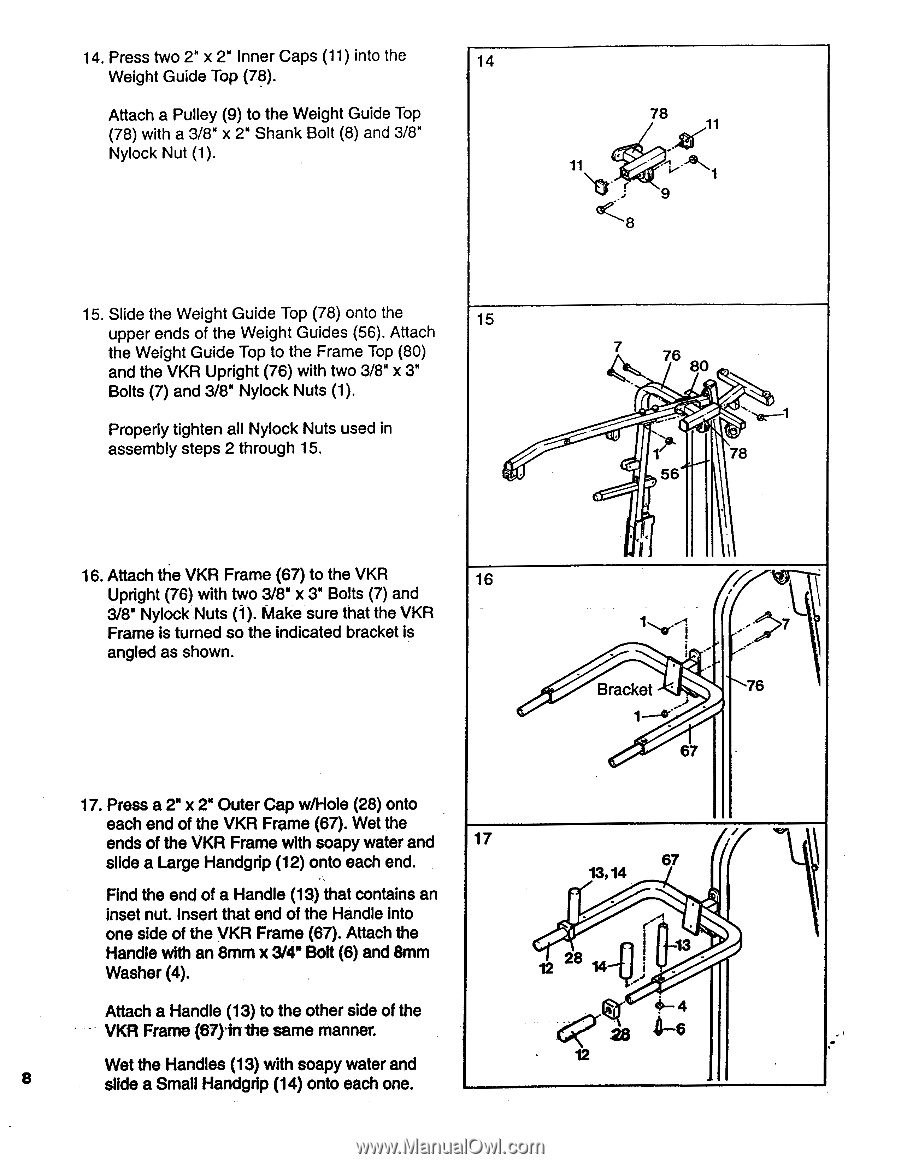
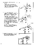
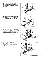
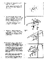
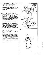
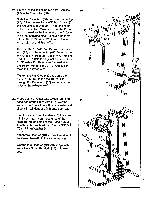
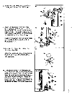
14. Press two 2" x 2" Inner Caps (11) into the 14 Weight Guide Top (78). Attach a Pulley (9) to the Weight Guide Top (78) with a 3/8" x 2" Shank Bolt (8) and 3/8" Nylock Nut (1). 78 • 11 11 .1., -• 1 - I ''' 9 8 15. Slide the Weight Guide Top (78) onto the 15 upper ends of the Weight Guides (56). Attach the Weight Guide Top to the Frame Top (80) and the VKR Upright (76) with two 3/8" x 3" Bolts (7) and 3/8" Nylock Nuts (1). Properly tighten all Nylock Nuts used in assembly steps 2 through 15. 47)I ,, 76 80 . --,a--,i .0. 1' 78 56 16. Attach the VKR Frame (67) to the VKR Upright (76) with two 3/8" x 3" Bolts (7) and 3/8" Nylock Nuts (1). Make sure that the VKR Frame is turned so the indicated bracket is angled as shown. 1. I 1 6,..- 1 Bracket ' 1- 0" 67 .,- 7 • 76 17. Press a 2" x 2" Outer Cap w/Hole (28) onto each end of the VKR Frame (67). Wet the ends of the VKR Frame with soapy water and 17 slide a Large Handgrip (12) onto each end. 67 \ 13,14 Find the end of a Handle (13) that contains an inset nut. Insert that end of the Handle into one side of the VKR Frame (67). Attach the Handle with an 8mm x 3/4" Bolt (6) and 8mm Washer (4). 12 28 r • I 13 Attach a Handle (13) to the other side of the VKR Frame (67)1111:he same manner. Wet the Handles (13) with soapy water and 8 slide a Small Handgrip (14) onto each one. ' 4- 4 4-6 • 12
-
 1
1 -
2
-
 3
3 -
 4
4 -
 5
5 -
 6
6 -
 7
7 -
 8
8 -
 9
9 -
 10
10 -
 11
11 -
 12
12 -
 13
13 -
14
-
15
-
16
-
17
-
18
-
19
-
20
-
21
-
22
-
23
-
24
 |
 |