ProForm 970 Ci English Manual - Page 9
outside
 |
View all ProForm 970 Ci manuals
Add to My Manuals
Save this manual to your list of manuals |
Page 9 highlights
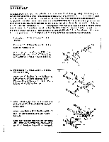
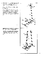
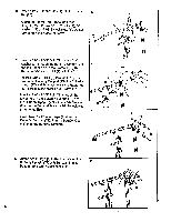
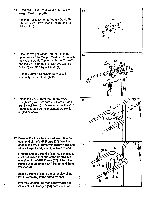
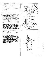
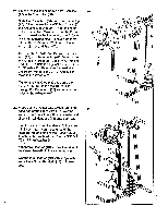
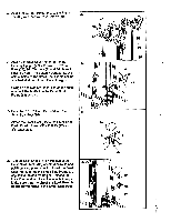
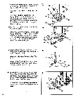
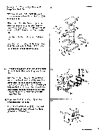
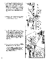
18. Attach the VKR Backrest (66) to the center of the VKR Frame (67) with two 8mm x 3/4" Bolts (6) and 8mm Washers (4). Attach the two VKR Armrests (65) to the VKR Frame (67) with 3/8" x 2" Bolts (17) and 3/8" Washers (2). 19. Insert a 3/8" x 3 1/2" Shank Bolt (25) into one side of the Adjuster (61). Slide a 3/4" x 3/4" Spacer (18), a Pulley (9) and another 3/4" x 3/4" Spacer onto the Bolt. Insert the Bolt through the other side of the Adjuster. Slide a 3/8" Washer (2) onto the Bolt and tighten a 3/8" Nylock Nut (1) onto the Bolt. Attach another Pulley (9) to the Adjuster (61) in the same manner. Insert the two Thick 5/8" Bushings (26) into the Adjuster (61) from the outside as shown. Grease the insides of the Bushings. Make sure that the Bushings remain in the Adjuster during assembly steps 24 and 25. 20. Press two 2" x 2" Inner Caps (11) into the posts on the Press Arm (88). lighten the Pin Knob (44) onto the 103/4" Pin (43). Hold the Adjuster (61) between the posts on the Press Arm (88) as shown. See the drawing at the right to make sure that the Adjuster is turned correctly-note the position of the long end of the Adjuster and the angle of the handles on the Press Arm. Insert the 103/4" Pin (43) through the Press Arm and one of the holes In the Adjuster. 18 65 67 6 4 6 17 65 19 26 Grease Grease sik -----.2..... 9 15 00 0 61 ()0000 18 18 9 20 11 88 61 Long End 43 . • • Handles 9
-
 1
1 -
2
-
3
-
 4
4 -
 5
5 -
 6
6 -
 7
7 -
 8
8 -
 9
9 -
 10
10 -
 11
11 -
 12
12 -
 13
13 -
 14
14 -
15
-
16
-
17
-
18
-
19
-
20
-
21
-
22
-
23
-
24
 |
 |
