ProForm 970 Ci English Manual - Page 15
ProForm 970 Ci Manual
 |
View all ProForm 970 Ci manuals
Add to My Manuals
Save this manual to your list of manuals |
Page 15 highlights
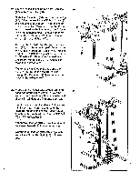
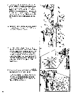
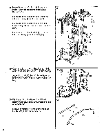
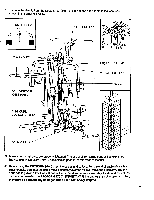
38. Route the end of Cable #1 (91) under the indicated pin on the Press Arm (88). Wrap 38 Pin the Cable around the upper Pulley (9) on the Adjuster (61). Lay Cable #1 (91) over a Pulley (9). Attach the Pulley to the indicated bracket on the 1 9 9 0 72 O 8 61 91 Front Upright (72) with a 3/8" x 2" Shank Bolt (8) and 3/8" Nylock Nut (1). 8 39. Wrap Cable #1 (91) around the lower Pulley (9) on the Adjuster (61). 39 Insert the end of Cable #1 (91) through the indicated hole in the Front Upright (72). Lay Cable #1 (91) over a Pulley (9). Attach the Pulley to the indicated bracket on the Front Upright (72) with a 3/8" x 2" Shank Bolt (8) and 3/8" Nylock Nut (1). 40. Attach two Pulleys (9) to one of the Swivel 40 Brackets (51) with 3/8" x 2" Shank Bolts (8) and 3/8" Nylock Nuts (1) (see the inset draw- ing). Attach two Pulleys (9) to the other Swivel Bracket (51) in the same manner (not shown). Route the end of Cable #1 (91) under one of the Pulleys (9) on one of the Swivel Brackets (51) as shown. Route the end of Cable #1 (91) over the Pulley (9) on the Weight Guide Top (78). Thread the bolt on the end of Cable #1 (91) about halfway into the Weight Selector (57). ••• J61 91 etc 72 9 0. a 90 8 I'll II II 111,!---.-11 78 9 91 9 51 91 57 Bolt 1 51 8 5
-
 1
1 -
2
-
3
-
4
-
5
-
6
-
7
-
8
-
9
-
 10
10 -
 11
11 -
 12
12 -
 13
13 -
 14
14 -
 15
15 -
 16
16 -
 17
17 -
 18
18 -
 19
19 -
 20
20 -
21
-
22
-
23
-
24
 |
 |
