ProForm 970 Ci English Manual - Page 12
ProForm 970 Ci Manual
 |
View all ProForm 970 Ci manuals
Add to My Manuals
Save this manual to your list of manuals |
Page 12 highlights
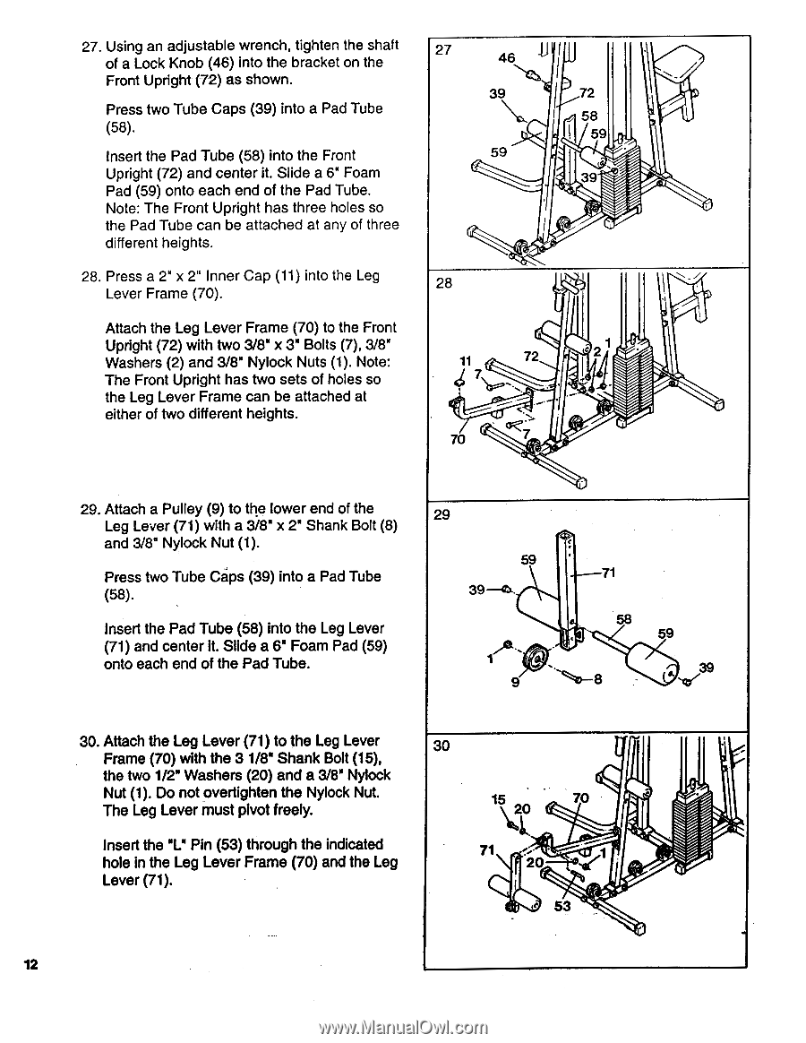
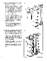
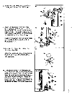
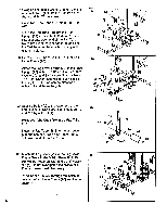
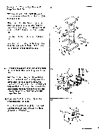
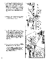
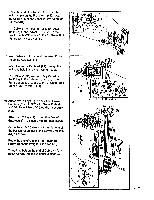
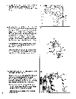
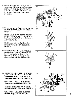
27. Using an adjustable wrench, tighten the shaft of a Lock Knob (46) into the bracket on the Front Upright (72) as shown. Press two Tube Caps (39) into a Pad Tube (58). Insert the Pad Tube (58) into the Front Upright (72) and center it. Slide a 6" Foam Pad (59) onto each end of the Pad Tube. Note: The Front Upright has three holes so the Pad Tube can be attached at any of three different heights. 28. Press a 2" x 2" Inner Cap (11) into the Leg Lever Frame (70). Attach the Leg Lever Frame (70) to the Front Upright (72) with two 3/8" x 3" Bolts (7), 3/8" Washers (2) and 3/8" Nylock Nuts (1). Note: The Front Upright has two sets of holes so the Leg Lever Frame can be attached at either of two different heights. 27 46 39 72 \z. 58 59 59 . 39 ' 28 .t..?: 1 . 117 t 72 S' 7 • . , c .- • 70 7 _ / . , _z 29. Attach a Pulley (9) to the lower end of the Leg Lever (71) with a 3/8" x 2" Shank Bolt (8) and 3/8" Nylock Nut (1). Press two Tube Caps (39) into a Pad Tube (58). Insert the Pad Tube (58) into the Leg Lever (71) and center it. Slide a 6" Foam Pad (59) onto each end of the Pad Tube. 29 59 71 39-Ok. Ilj, A -- • 58 59 30. Attach the Leg Lever (71) to the Leg Lever Frame (70) with the 31/8" Shank Bolt (15), the two 1/2" Washers (20) and a 3/8" Nylock Nut (1). Do not overtighten the Nylock Nut. The Leg Lever must pivot freely. Insert the "L" Pin (53) through the indicated hole in the Leg Lever Frame (70) and the Leg Lever (71). 30 I 15 70 20 71 ;• • 2 -( Ab 53 . 12 , . .
-
 1
1 -
2
-
3
-
4
-
5
-
6
-
 7
7 -
 8
8 -
 9
9 -
 10
10 -
 11
11 -
 12
12 -
 13
13 -
 14
14 -
 15
15 -
 16
16 -
 17
17 -
18
-
19
-
20
-
21
-
22
-
23
-
24
 |
 |