Ricoh ISO1 Operation Manual - Page 56
RS-232C Interface
 |
View all Ricoh ISO1 manuals
Add to My Manuals
Save this manual to your list of manuals |
Page 56 highlights
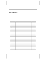
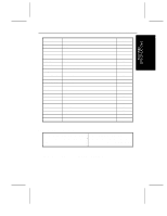
SCANNER SPECIFICATIONS RS-232C Interface This interface is provided for connection of the optional Operation Panel. It requires a standard RS-232C cross cable (3 meters maximum length) for connection. The scanner side of the cable should have a 25-pin male connector, while the other end of the cable should have a connector that matches the needs of your host computer. The table below lists pin assignments for the RS-232C interface. RS-232C pin assignments Code Signal Pin FG Frame Ground 1 TXD Transfer Data 2 RXD Receive Data 3 SG Signal Ground 7 All other pins of the RS-232C interface are not connected. 5-6
-
 1
1 -
2
-
3
-
4
-
5
-
6
-
7
-
8
-
9
-
10
-
11
-
12
-
13
-
14
-
15
-
16
-
17
-
18
-
19
-
20
-
21
-
22
-
23
-
24
-
25
-
26
-
27
-
28
-
29
-
30
-
31
-
32
-
33
-
34
-
35
-
36
-
37
-
38
-
39
-
40
-
41
-
42
-
43
-
44
-
45
-
46
-
47
-
48
-
49
-
50
-
 51
51 -
 52
52 -
 53
53 -
 54
54 -
 55
55 -
 56
56 -
 57
57 -
 58
58 -
 59
59 -
 60
60 -
 61
61 -
62
-
63
-
64
-
65
-
66
-
67
-
68
-
69
-
70
-
71
-
72
-
73
-
74
-
75
-
76
-
77
-
78
-
79
-
80
 |
 |

SCANNER SPECIFICATIONS
5-6
RS-232C Interface
This interface is provided for connection of the optional Operation Panel. It
requires a standard RS-232C cross cable (3 meters maximum length) for
connection. The scanner side of the cable should have a 25-pin male connector,
while the other end of the cable should have a connector that matches the needs
of your host computer.
The table below lists pin assignments for the RS-232C interface.
RS-232C pin assignments
Code
Signal
Pin
FG
Frame Ground
1
TXD
Transfer Data
2
RXD
Receive Data
3
SG
Signal Ground
7
All other pins of the RS-232C interface are not connected.