Ridgid R4510 Operation Manual - Page 27
To Change Blade Depth, To Change Blade Angle, To Adjust The Bevel Indicator, To Use The Ind-i-cut
 |
View all Ridgid R4510 manuals
Add to My Manuals
Save this manual to your list of manuals |
Page 27 highlights
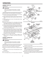
OPERATION TO CHANGE BLADE DEPTH See Figure 32. The blade depth should be set so that the outer points of the saw blade are higher than the workpiece by approximately 1/8 in. to 1/4 in. but the lowest points (gullets) are below the workpiece. Unlock the blade height lock knob. Raise the saw blade by turning the height adjusting knob clockwise or lower it by turning the knob counterclockwise. Once the desired saw blade height is achieved, lock the blade height lock knob by turning it clockwise. TO CHANGE BLADE ANGLE See Figure 33. NOTE: A 90° cut has a 0° bevel and a 45° cut has a 45° bevel. Unplug the saw. Unlock bevel locking lever by pulling the lever all the way to the right. Adjust the bevel angle, turning the handwheel counterclockwise increases the angle of the blade, bringing it closer to 45°. Turning it clockwise decreases the angle, bringing the blade closer to 90°. NOTE: When the bevel adjusting handwheel is pushed back towards the saw housing and released, the bevel angle can be quickly changed by pushing the handwheel left or right. Lock bevel locking lever by pushing lever to the left. TO ADJUST THE BEVEL INDICATOR See Figure 34. If the bevel indicator is not at zero when the saw blade is at 90°, adjust the indicator by loosening the screws and setting at 0° on the bevel scale. Retighten the screws. TO USE THE IND-I-CUT See Figure 35. The plastic disc embedded in the saw table in front of the saw blade is provided for marking the location of the saw cut (kerf) on the workpiece. The disc should be level or slightly below the surface of the saw table. Place a piece of hardwood over the plastic disc and tap the hardwood with a hammer until the disc is level or below the saw table surface. Once the Ind-I-Cut is level: From the front of the table saw, place the miter gauge in the left miter groove and move the bevel adjusting handwheel until the bevel scale is set at 0°. Turn on the table saw and cross cut a piece of wood holding the wood firmly against the miter gauge. Turn off the table saw. Once the blade has stopped, pull the miter gauge back until the freshly cut wood is over the disc. GULLET TO LOCK BEVEL LOCKING LEVER Fig. 32 TO UNLOCK HEIGHT ADJUSTING KNOB BLADE HEIGHT LOCK KNOB TO INCREASE ANGLE BEVEL LOCKING LEVER TO DECREASE ANGLE BEVEL ADJUSTING HANDWHEEL Fig. 33 SCREWS BEVEL INDICATOR Fig. 35 27
-
 1
1 -
2
-
3
-
4
-
5
-
6
-
7
-
8
-
9
-
10
-
11
-
12
-
13
-
14
-
15
-
16
-
17
-
18
-
19
-
20
-
21
-
 22
22 -
 23
23 -
 24
24 -
 25
25 -
 26
26 -
 27
27 -
 28
28 -
 29
29 -
 30
30 -
 31
31 -
 32
32 -
33
-
34
-
35
-
36
-
37
-
38
-
39
-
40
-
41
-
42
-
43
-
44
-
45
-
46
-
47
-
48
 |
 |
