Ridgid R4510 Operation Manual - Page 28
To Set The Rip Fence Indicator To The, Blade, To Use The Rip Fence
 |
View all Ridgid R4510 manuals
Add to My Manuals
Save this manual to your list of manuals |
Page 28 highlights
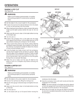
OPERATION Using a sharp pencil, mark a line on the disc at the edge of the freshly cut wood. NOTE: These lines indicate the path of the cut made by the saw blade. When the blade is changed, these lines will need to be erased and reset. With the miter gauge in the right miter gauge groove, follow the above procedures and make a second mark on the disc. TO SET THE RIP FENCE INDICATOR TO THE BLADE See Figure 36. Use the indicator on the rip fence to position the fence along the scale on the front rail. NOTE: The anti-kickback pawls and blade guard assembly must be removed to perform this adjustment. Reinstall the blade guard assembly when the adjustment is complete. Unplug the saw. Place the rip fence on the saw table so that it lightly touches the right side of the saw blade. Lock the rip fence in place. Loosen pan head screws and adjust the indicator so that the red line is located over the "zero" line on the right rip scale on the front rail. Retighten screws. TO USE THE RIP FENCE See Figures 36 - 37. Place the front of the rip fence on the front rail. Lower the back end of the rip fence onto the back rail. Check for smooth gliding action. Position the rip fence the desired distance from the blade. Push the locking lever down to automatically align and secure the fence. When securely locked, the locking lever should point downward. Check for a smooth gliding action. If adjustments are needed, see To Check and Adjust the Alignment of the Rip Fence in the Adjustments section of this manual. IND-I-CUT INDICATOR Fig. 35 0 2 3 PAN HEAD SCREW Fig. 36 BACK RAIL BACK OF RIP FENCE Fig. 37 28
-
 1
1 -
2
-
3
-
4
-
5
-
6
-
7
-
8
-
9
-
10
-
11
-
12
-
13
-
14
-
15
-
16
-
17
-
18
-
19
-
20
-
21
-
22
-
 23
23 -
 24
24 -
 25
25 -
 26
26 -
 27
27 -
 28
28 -
 29
29 -
 30
30 -
 31
31 -
 32
32 -
 33
33 -
34
-
35
-
36
-
37
-
38
-
39
-
40
-
41
-
42
-
43
-
44
-
45
-
46
-
47
-
48
 |
 |
