Ridgid R4510 Operation Manual - Page 30
Heeling Paralleling The Blade To The, Miter Gauge Groove, Warning
 |
View all Ridgid R4510 manuals
Add to My Manuals
Save this manual to your list of manuals |
Page 30 highlights
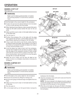
OPERATION HEELING (PARALLELING) THE BLADE TO THE MITER GAUGE GROOVE See Figures 41 - 43. WARNING: The blade must be square so the wood does not bind resulting in kickback. Failure to do so could result in serious personal injury. Do not loosen any screws for this adjustment until you have checked with a square and made test cuts to be sure adjustments are necessary. Once the screws are loosened, these items must be reset. Unplug the saw. Remove the blade guard and anti-kickback pawls. Raise the blade by turning the bevel adjusting handwheel. Mark beside one of the blade teeth at the front of the blade. Place the body of a combination square against the miter gauge groove as shown in figure 41. Measure the distance from the blade tooth to the right miter gauge groove. Turn the blade so the marked tooth is at the back. Move the combination square to the rear and again measure the distance from the blade tooth to the right miter gauge groove. If the distances are the same, the blade and the miter gauge groove are parallel. Loosen the four alignment screws 1/2 turn; this allows the mechanism beneath the table to be shifted sideways. NOTE: The adjustment screws are located on the top of the saw table next to the blade. Place a block of wood on the side of the blade and push it into the blade until the blade is parallel to the miter gauge groove. Retighten one screw. Check with square to determine if marked tooth touches square by the same amount at front and rear. If it does, alternately tighten other three screws. If it does not, loosen screw and move blade the required amount. WARNING: To reduce the risk of injury from kickback, align the rip fence to the blade following any blade adjustments. Always make sure the rip fence is parallel to the blade before beginning any operation. 30 MITER GAUGE GROOVE COMBINATION SQUARE Fig. 41 MITER GAUGE COMBINATION GROOVE SQUARE ALIGNMENT SCREWS Fig. 42 ALIGNMENT SCREWS Fig. 43
-
 1
1 -
2
-
3
-
4
-
5
-
6
-
7
-
8
-
9
-
10
-
11
-
12
-
13
-
14
-
15
-
16
-
17
-
18
-
19
-
20
-
21
-
22
-
23
-
24
-
 25
25 -
 26
26 -
 27
27 -
 28
28 -
 29
29 -
 30
30 -
 31
31 -
 32
32 -
 33
33 -
 34
34 -
 35
35 -
36
-
37
-
38
-
39
-
40
-
41
-
42
-
43
-
44
-
45
-
46
-
47
-
48
 |
 |
