Ridgid R4510 Operation Manual - Page 29
To Use The Micro-adjust Wheel On The, Rip Fence, To Use The Miter Gauge, To Use The Sliding Table - table extension
 |
View all Ridgid R4510 manuals
Add to My Manuals
Save this manual to your list of manuals |
Page 29 highlights
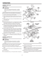
OPERATION TO USE THE MICRO-ADJUST WHEEL ON THE RIP FENCE See Figure 38. The micro-adjust wheel on the rip fence allows the user to make one-handed adjustments. Unlock the locking lever by lifting the lever. Push in on the micro-adjust wheel and rotate to the de- sired location. Push the locking lever downward to lock the rip fence into place. TO USE THE MITER GAUGE See Figure 39. The miter gauge provides greater accuracy in angled cuts. For very close tolerances, test cuts are recommended. There are two miter gauge channels, one on either side of the blade. When making a 90° cross cut, you can use either miter gauge channel. When making a beveled cross cut (the blade tilted in relation to the table) the miter gauge should be located in the slot on the right so that the blade is tilted away from the miter gauge and your hands. The miter gauge can be turned 60° to the right or left. Positive stops at 0° and 45° can be located by pushing in the stop pin. Slide the miter gauge in the miter gauge slot. Loosen the lock knob by turning it counterclockwise. Pull out the stop pin and rotate the gauge until the desired angle is reached on the scale. Retighten the lock knob by turning it clockwise. TO USE THE SLIDING TABLE EXTENSION See Figure 40. Increase the length of the saw table by using the sliding table extension. Remove the rip fence. Unlock the sliding table extension by lifting the table extension lock lever. Slide the table extension to the desired width. NOTE: Use the scale on the front rail when a specific width is desired. Once the extension table is set to the desired width, relock the lever by pushing the lever back towards the saw base. NOTE: When using the table extended, only set the fence beyond the arrow marked on the label on the rear rail. MITER GAUGE MICRO-ADJUST WHEEL LOCKING LEVER Fig. 38 LOCK KNOB POSITIVE STOPS TO UNLOCK STOP PIN Fig. 39 SLIDING TABLE EXTENSION TABLE EXTENSION LOCK LEVER Fig. 40 29
-
 1
1 -
2
-
3
-
4
-
5
-
6
-
7
-
8
-
9
-
10
-
11
-
12
-
13
-
14
-
15
-
16
-
17
-
18
-
19
-
20
-
21
-
22
-
23
-
 24
24 -
 25
25 -
 26
26 -
 27
27 -
 28
28 -
 29
29 -
 30
30 -
 31
31 -
 32
32 -
 33
33 -
 34
34 -
35
-
36
-
37
-
38
-
39
-
40
-
41
-
42
-
43
-
44
-
45
-
46
-
47
-
48
 |
 |
