Ryobi BS903 BS903_979_trillingual.pdf - Page 13
Adjustments, Operation - band saw blades
 |
View all Ryobi BS903 manuals
Add to My Manuals
Save this manual to your list of manuals |
Page 13 highlights
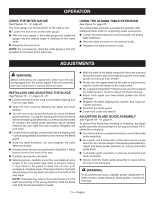
OPERATION USING THE MITER GAUGE See Figures 13 - 14, page 20. The miter gauge can be turned 60° to the right or left. Loosen the lock knob on the miter gauge. With the miter gauge in the miter gauge slot, rotate the gauge until the desired angle is reached on the index scale. Retighten the lock knob. NOTE: For convenience, store the miter gauge in the slot provided on the back of the band saw. using the sliding table extension See Figure 15, page 20. The sliding table extension provides the operator with additional table width for supporting wider workpieces. Loosen the table extension knobs beneath the sliding table extension. Slide the table extension to the desired width. Retighten the table extension knobs. ADJUSTMENTS WARNING: Before performing any adjustment, make sure the tool is unplugged from the power supply. Failure to heed this warning could result in serious personal injury. INSTALLING AND ADJUSTING THE BLADE See Figures 16 - 17, pages 20 - 21. Loosen and remove the wing nut and table aligning bolt from the saw table. Open the front cover by releasing the upper and lower latches. Turn the lock knob counterclockwise to unlock the blade guide assembly. Turning the blade guide knob (clockwise raises the blade guide assembly; counterclockwise lowers it), position the blade guide assembly about halfway between the saw table and saw housing. Retighten the lock knob. Loosen the two phillips screws that hold the blade guard in place using phillips screwdriver, then remove the blade guard. Slide the table extension out and retighten the table extension knobs. Release blade tension by pushing the RapidSet™ blade tension lever to the front of the saw. Carefully remove the old blade. Wearing gloves, carefully uncoil the new blade at arms length. If the new blade was oiled to prevent rusting, it may need to be wiped to keep the oil from your workpiece. Carefully wipe in the same direction the teeth are pointing so the rag does not catch on the teeth of the saw blade. Note: The blade may need to be turned inside out if the teeth are pointing in the wrong direction. Hold the blade with both hands and rotate it inward. With the teeth of the blade toward the left of the saw and facing downward, place the blade through the lower blade guides and around both wheels. Slowly turn the upper wheel to the right or clockwise by hand to center the blade on the rubber tires. Re-engage the RapidSet™ blade tension lever then adjust the blade tension; check or adjust the blade tracking. Adjust both upper and lower blade guides and thrust bearings. Reattach the table aligning bolt, washer, and wing nut. Tighten securely. Reattach the blade guard. Close front cover and relatch. adjusting blade guide assembly See Figures 18 - 19, page 21. To prevent the blade from twisting or breaking, the blade guide assembly should always be set approximately 1/8 in. above the workpiece. Turn the lock knob counterclockwise to unlock the blade guide assembly. As a guide, use a scrap piece of the same wood you are about to cut to set the height of the blade guide assembly. Adjust the blade guide assembly by turning the blade guide knob. Lock blade guide assembly in place by turning the lock knob clockwise. Always lock the blade guide assembly in place before turning on the band saw. warning: To avoid personal injury, maintain proper adjustment of blade tension, blade tracking, blade guides, and thrust bearings. 13 - English
-
 1
1 -
2
-
3
-
4
-
5
-
6
-
7
-
 8
8 -
 9
9 -
 10
10 -
 11
11 -
 12
12 -
 13
13 -
 14
14 -
 15
15 -
 16
16 -
 17
17 -
 18
18 -
19
-
20
-
21
-
22
-
23
-
24
-
25
-
26
-
27
-
28
-
29
-
30
-
31
-
32
-
33
-
34
-
35
-
36
-
37
-
38
-
39
-
40
-
41
-
42
-
43
-
44
-
45
-
46
-
47
-
48
-
49
-
50
-
51
-
52
-
53
-
54
-
55
-
56
 |
 |