Samsung PPM50H3 User Manual - Page 7
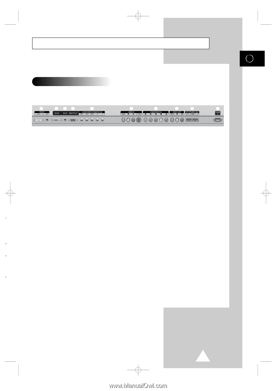
Rear Panel, Dvi In, Audio, Rgb1pc1 In, Component2/rgb2pc2 In, Video In, Component1 In, Video Out Video
 |
UPC - 770332800134
View all Samsung PPM50H3 manuals
Add to My Manuals
Save this manual to your list of manuals |
Page 7 highlights
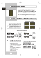
BN68-00654A-01Eng 4/19/04 4:12 PM Page 7 Your New Plasma Display Panel ➢ The actual configuration on your PDP may be different, depending on your model. ENG Rear Panel ➢ For further details about connection, refer to pages 35~37. a b cd e f g h i j a) RS232C - IN : Used for the MDC function when connecting PC or RS232C output of another PDP. - OUT : Used for the MDC function when connecting with RS232C input of another PDP. b) DVI IN Connect to the video output jack for device with DVI output. c) AUDIO Connect to the audio output jack on your PC or any device with DVI output. (It is audio input for b, d, and e.) d) RGB1(PC1) IN Connect to the video output jack on your PC. e) COMPONENT2/RGB2(PC2) IN Connect for input of an Analog RGB or Y/Pb/Pr video signal from in PC, DVD, or HD devices. ➢ "PC Mode" from this page onward means PC1/PC2 mode using RGB1(PC1) and RGB2(PC2). f) VIDEO IN Video and audio inputs for external devices, such as VCR, DVD, video game device or video disc players (or for external devices with an S-Video output; S-VIDEO). g) COMPONENT1 IN Video (Y/Pb/Pr) and audio (L/R) inputs for component. h) VIDEO OUT (VIDEO / L-AUDIO-R) Used to output screen of Video or S-Video in PDP when connecting video and/or audio input of external devices. i) EXT SPEAKER (8Ω) Connect external speakers. j) POWER IN Connect the supplied power cord. 7
-
 1
1 -
 2
2 -
 3
3 -
 4
4 -
 5
5 -
 6
6 -
 7
7 -
 8
8 -
 9
9 -
 10
10 -
 11
11 -
 12
12 -
13
-
14
-
15
-
16
-
17
-
18
-
19
-
20
-
21
-
22
-
23
-
24
-
25
-
26
-
27
-
28
-
29
-
30
-
31
-
32
-
33
-
34
-
35
-
36
-
37
-
38
-
39
-
40
-
41
-
42
-
43
-
44
 |
 |