Sanyo 24KHS72 Service Manual - Page 33
Electric Wiring Diagrams
 |
View all Sanyo 24KHS72 manuals
Add to My Manuals
Save this manual to your list of manuals |
Page 33 highlights
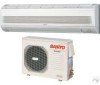
6-2. Electric Wiring Diagrams Indoor Unit KHS1872 KHS2472 To avoid electrical shock hazard, be sure to WARNING disconnect power before checking, servicing and/or cleaning any electrical parts. TO OUTDOOR UNIT EVAPORATOR TERMINAL BASE BLK 1 WHT 2 RED 3 GRN/YEL IND LAMP ASSY CONNECTOR 1 1 RED 2 2 PNK FLAP 3 3 BLU 4 4 BRN 5 5 YEL FLAP MOTOR AC1 AC2 SI 1 1 11 22 2 3 4 5 2 3 4 5 FLAP 5P (WHT) LAMP 10P(WHT) 3 4 5 6 3 4 5 6 77 88 99 10 10 RED WHT WHT WHT WHT WHT WHT WHT WHT WHT 11 22 33 44 55 66 77 88 99 10 10 FM FAN MOTOR CONTROLLER RED BLK WHT YEL BLU ROOM THERMISTOR 11 11 2 3 4 2 3 4 ROOM/COIL DCM 4P(WHT) 6P(BLU) 2 3 4 2 3 4 55 66 BLK BLK BLK BLK COIL THERMISTOR 11 ION 3P (WHT) 2 3 2 3 HA JEM-A 4P (WHT) 1234 ION TERMINAL 1234 1234 ION ASSY BLK BLK BLK RED WHT 8FA2-5257-70500-0 33
-
 1
1 -
2
-
3
-
4
-
5
-
6
-
7
-
8
-
9
-
10
-
11
-
12
-
13
-
14
-
15
-
16
-
17
-
18
-
19
-
20
-
21
-
22
-
23
-
24
-
25
-
26
-
27
-
 28
28 -
 29
29 -
 30
30 -
 31
31 -
 32
32 -
 33
33 -
 34
34 -
 35
35 -
 36
36 -
 37
37 -
 38
38 -
39
-
40
-
41
-
42
-
43
-
44
-
45
-
46
-
47
-
48
-
49
-
50
-
51
-
52
-
53
-
54
-
55
-
56
-
57
-
58
-
59
-
60
-
61
-
62
-
63
-
64
-
65
-
66
-
67
-
68
-
69
-
70
-
71
-
72
-
73
-
74
-
75
-
76
-
77
-
78
-
79
-
80
-
81
-
82
-
83
-
84
-
85
-
86
-
87
-
88
-
89
-
90
-
91
-
92
-
93
-
94
-
95
-
96
-
97
-
98
-
99
-
100
-
101
-
102
-
103
-
104
-
105
-
106
-
107
-
108
-
109
-
110
-
111
 |
 |
