Sharp PG-D210U PGD210U Operation Manual - Page 8
Caution - model #
 |
View all Sharp PG-D210U manuals
Add to My Manuals
Save this manual to your list of manuals |
Page 8 highlights
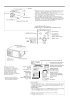
TOP VIEW REMOTE CONTROL SIGNAL TRANSMITTER WIRED REMOTE CONTROL INPUT (3.5 mm Minijack) LASER LIGHT WINDOW Laser light shines out of this window. CAUTION LASER RADIATIONDO NOT STARE INTO BEAM WAVE LENGTH : 670nm MAX. OUTPUT : 1mW CLASS II LASER PRODUCT "COMPLIES WITH 21 CFR SUBCHAPTER J" SHARP ELECTRONICS CORPORATION SHARP PLAZA, MAHWAH, NEW JERSEY 07430 TEL : 1-800-BE-SHARP U.S.A. ONLY REMOTE CONTROL MODEL NO. : G1414CESA DC6V (1.5VX4PCS.) MADE IN JAPAN FABRIQUÉ AU JAPON Using the optional cable with the remote control When the remote control cannot be used due to the range or positioning of the projector (rear projection, etc.), connect the optional cable from the Wired Remote Control Input jack on the remote control to the Wired Remote Input on the rear of the projector. Note: • The signal transmitter does not function when the optional cable is connected to the remote control. The laser pointer on the remote control emits a laser beam from the laser light window shown in the figure to the left. The laser emitted is a class II laser; therefore, do not look into the laser window or shine the laser beam on yourself or other people. The two marks to the left are the caution labels for the laser beam. Always use the laser pointer at temperatures between 41°F and 104°F (ם5°C and ם40°C). REAR VIEW Press in and downward on the arrow mark and remove. Insert the side tabs into their slots and press in the cover until properly seated. Transmission range Reception range 30° 30° Max. distance: 23 (7 m) Inserting the batteries Remove the battery cover as shown and insert four AA size batteries making sure their polarities match the ()ם and ( )מmarks inside the battery compartment. Notes: Incorrect use of batteries may cause them to leak or burst. • Insert the batteries with the ( )םand ( )מpolarities as indi- cated. • Remove the batteries if the remote control will not be oper- ated for an extended period of time. • Maintain the batteries in a clean condition. • Do not mix different brands of batteries. The life expectancy of the new batteries will be shortened and the old batteries may leak. • When the batteries have been used up, remove them immediately to prevent leakage and damage. Leaked battery fluid may irritate the skin. Remove any battery fluid by wiping with a cloth. • Due to storage conditions and the shelf life of the supplied batteries, they may run out after a short time. If so, replace them with new batteries as soon as possible. Remote control positioning Use the remote control as shown in the figures on the left. Note: • The signal from the remote control can be reflected off the screen for easy operation. However, the effective distance of the signal may differ due to the screen material. 45° 30° E-7
-
 1
1 -
2
-
 3
3 -
 4
4 -
 5
5 -
 6
6 -
 7
7 -
 8
8 -
 9
9 -
 10
10 -
 11
11 -
 12
12 -
 13
13 -
14
-
15
-
16
-
17
-
18
-
19
-
20
-
21
-
22
-
23
-
24
-
25
-
26
-
27
-
28
-
29
-
30
-
31
-
32
-
33
-
34
-
35
-
36
-
37
-
38
-
39
-
40
 |
 |
