Sharp PN-L702B PN-L702B Professional LCD Monitor Operation Manual - Page 36
RS-232C command table, Power control/Input mode selection, Controlling the Monitor with a PC RS-232C
 |
View all Sharp PN-L702B manuals
Add to My Manuals
Save this manual to your list of manuals |
Page 36 highlights
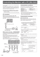
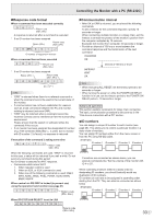
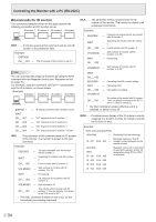
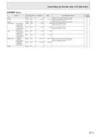
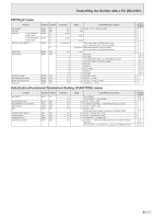
Controlling the Monitor with a PC (RS-232C) RS-232C command table How to read the command table Command: Direction: Parameter: Reply: *1: *2: Command field (See page 32.) W When the "Parameter" is set in the parameter field (see page 32), the command functions as described under "Control/Response Contents". R The returned value indicated under "Reply" can be obtained by setting "????", " ?" or "???+" (repeater control) in the parameter field (see page 32). Parameter field (See page 32.) Response (Returned value) "●" indicates a command which can be used in power standby mode regardless of the STANDBY MODE setting. "○" indicates a command which cannot be used in power standby mode when STANDBY MODE is set to LOW POWER. "-" indicates a command which cannot be used in power standby mode regardless of the STANDBY MODE setting. PN-ZB01 (optional) limitations (A) When PN-ZB01 (optional) is not attached, (B) When PN-ZB01 (optional) is attached. ○ : The command can be used. - : Error (ERR) Power control/Input mode selection Function POWER CONTROL Command Direction POWR W R Parameter 0 1 INPUT MODE SELECTION INPS W 0 1 2 3 4 6 7 8 9 10 R Reply Control/Response contents *2 *1 (A) (B) Switches to standby mode. Returns from standby mode. 0 Standby mode 1 Normal mode ●○○ 2 Input signal waiting mode Toggle change for input mode. Terminals not selected in INPUT SELECT cannot be selected. ○○ PC DVI-D "ERR" when AV DVI-D is selected for DVI of INPUT SELECT. -○ PC D-SUB "ERR" when other than PC D-SUB is selected for D-SUB of INPUT SELECT. ○○ AV COMPONENT (BNC) / AV COMPONENT (D-SUB) "ERR" when other than PC RGB is selected for BNC of INPUT SELECT, and ○○ when other than AV COMPONENT is selected for D-SUB of INPUT SELECT. AV VIDEO (BNC) / AV VIDEO (D-SUB) ●○○ PC RGB "ERR" when AV COMPONENT is selected for BNC of INPUT SELECT. -○ AV DVI-D "ERR" when PC DVI-D is selected for DVI of INPUT SELECT. AV S-VIDEO AV HDMI "ERR" when PC HDMI is selected for HDMI of INPUT SELECT. PC HDMI "ERR" when AV HDMI is selected for HDMI of INPUT SELECT. ○○ 1 PC DVI-D 2 PC D-SUB 3 AV COMPONENT 4 AV VIDEO 6 PC RGB 7 AV DVI-D ●○○ 8 AV S-VIDEO 9 AV HDMI 10 PC HDMI E 36
-
 1
1 -
2
-
3
-
4
-
5
-
6
-
7
-
8
-
9
-
10
-
11
-
12
-
13
-
14
-
15
-
16
-
17
-
18
-
19
-
20
-
21
-
22
-
23
-
24
-
25
-
26
-
27
-
28
-
29
-
30
-
 31
31 -
 32
32 -
 33
33 -
 34
34 -
 35
35 -
 36
36 -
 37
37 -
 38
38 -
 39
39 -
 40
40 -
 41
41 -
42
-
43
-
44
-
45
-
46
-
47
-
48
-
49
-
50
-
51
-
52
-
53
-
54
-
55
-
56
-
57
-
58
 |
 |