Sharp PN-L702B PN-L702B Professional LCD Monitor Operation Manual - Page 41
PIP/PbyP menu, Initialization/Functional Restriction Setting FUNCTION menu, Controlling the Monitor
 |
View all Sharp PN-L702B manuals
Add to My Manuals
Save this manual to your list of manuals |
Page 41 highlights
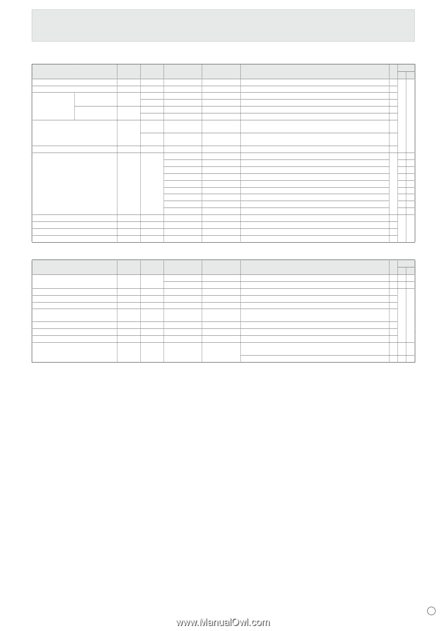
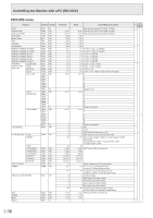
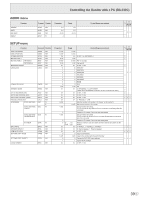
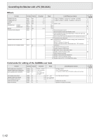
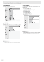
Controlling the Monitor with a PC (RS-232C) PIP/PbyP menu Function Command Direction PIP MODES MWIN WR PIP SIZE MPSZ WR PIP POS The longest MHPS W direction R The shortest MVPS W direction R PIP POS LD+SD BATCH MPOS W R PIP BLEND PIP SOURCE MWBL WR MWIP WR SOUND CHANGE MAIN POS (Main screen) PbyP2 POS (Sub screen) AUTO OFF MWAD WR MWPP WR MW2P WR MOFF WR Parameter 0-3 1-64 0-100 0-100 0-100,0-100 0-15 1 2 3 4 6 7 8 9 10 1-2 0-1 0-2 0-1 Reply Control/Response contents 0-3 0: OFF, 1: PIP, 2: PbyP, 3: PbyP2 1-64 0-100 0-100 Specify the position in MPOSxxxyyy format. (xxx: Longer side, yyy: Shorter side position) 0-100,0-100 Returns a response in (xxx,yyy) format. (xxx: Longer side, yyy: Shorter side position) 0-15 1 PC DVI-D 2 PC D-SUB 3 AV COMPONENT (BNC) / AV COMPONENT (D-SUB) 4 AV VIDEO (BNC) / AV VIDEO (D-SUB) 6 PC RGB 7 AV DVI-D 8 AV S-VIDEO 9 AV HDMI 10 PC HDMI 1-2 1: MAIN, 2: SUB 0-1 0: POS1, 1: POS2 0-2 0: POS1, 1: POS2, 2: POS3 0-1 0: MANUAL, 1: AUTO Initialization/Functional Restriction Setting (FUNCTION) menu Function ALL RESET ADJUSTMENT LOCK ADJUSTMENT LOCK TARGET OSD DISPLAY LED TEMPERATURE ALERT STATUS ALERT POWER BUTTON CONTROLLER INPUT Command Direction RSET W ALCK WR ALTG WR LOSD WR OFLD WR TALT WR SALT WR PBTN WR PCIP WR Parameter 0 0-1 0-2 0-2 0-2 0-1 0-2 0-2 0-1 0-2 Reply Control/Response contents 0: ALL RESET 0: ALL RESET 1, 1: ALL RESET 2 0-2 0: OFF, 1:ON1, 2:ON2 0-2 0: REMOTE CONTROL, 1: MONITOR BUTTONS, 2: BOTH 0-2 0: ON1, 1: OFF, 2: ON2 0-1 0: ON, 1: OFF "ERR" when LOW POWER is selected for STANDBY MODE. 0-2 0: OFF, 1: OSD & LED, 2: LED 0-2 0: OFF, 1: OSD & LED, 2: LED 0-1 0: MONITOR, 1: CONTROLLER 0-2 0: D-SUB, 1: HDMI ("ERR" when MONITOR is selected for POWER BUTTON.) 2: DVI-D ("ERR" when MONITOR is selected for POWER BUTTON.) *2 *1 (A) (B) ○ ○ ○ -○ ○○ ○○ ○○ ○-○ -○ -○ ○○ ○○ ○ ○ ○ ○ ○ ○ *2 *1 (A) (B) 41 E
-
 1
1 -
2
-
3
-
4
-
5
-
6
-
7
-
8
-
9
-
10
-
11
-
12
-
13
-
14
-
15
-
16
-
17
-
18
-
19
-
20
-
21
-
22
-
23
-
24
-
25
-
26
-
27
-
28
-
29
-
30
-
31
-
32
-
33
-
34
-
35
-
 36
36 -
 37
37 -
 38
38 -
 39
39 -
 40
40 -
 41
41 -
 42
42 -
 43
43 -
 44
44 -
 45
45 -
 46
46 -
47
-
48
-
49
-
50
-
51
-
52
-
53
-
54
-
55
-
56
-
57
-
58
 |
 |