Sony HCD-ZUX9 Service Manual - Page 16
CN381 3P, CN380 8P, top case wire flat type 11 core, CN101
 |
View all Sony HCD-ZUX9 manuals
Add to My Manuals
Save this manual to your list of manuals |
Page 16 highlights
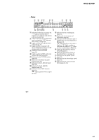
HCD-ZUX9 Note: Follow the disassembly procedure in the numerical order given. 3-1. SIDE R PANEL, SIDE L PANEL 7 screw (case 3 TP2) 0 side L panel 8 three screws (+BVTP 3 × 8) 9 6 two screws (case 3 TP2) 3 three screws (+BVTP 3 × 8) 2 screw (case 3 TP2) 3-2. TOP CASE SECTION 5 CN380 (8P) 4 5 side R panel 1 two screws (case 3 TP2) 1 four screws (+BVTP 3 × 8) 2 6 top case section 3 wire (flat type) (11 core) (CN101) 4 CN381 (3P) 16
-
 1
1 -
2
-
3
-
4
-
5
-
6
-
7
-
8
-
9
-
10
-
 11
11 -
 12
12 -
 13
13 -
 14
14 -
 15
15 -
 16
16 -
 17
17 -
 18
18 -
 19
19 -
 20
20 -
 21
21 -
22
-
23
-
24
-
25
-
26
-
27
-
28
-
29
-
30
-
31
-
32
-
33
-
34
-
35
-
36
-
37
-
38
-
39
-
40
-
41
-
42
-
43
-
44
-
45
-
46
-
47
-
48
-
49
-
50
-
51
-
52
-
53
-
54
-
55
-
56
-
57
-
58
-
59
-
60
-
61
-
62
-
63
-
64
-
65
-
66
-
67
-
68
-
69
-
70
-
71
-
72
-
73
-
74
-
75
-
76
-
77
-
78
-
79
-
80
-
81
-
82
-
83
-
84
-
85
-
86
-
87
-
88
-
89
-
90
-
91
-
92
-
93
-
94
-
95
-
96
-
97
-
98
-
99
-
100
-
101
-
102
-
103
-
104
-
105
-
106
-
107
-
108
-
109
-
110
-
111
-
112
-
113
-
114
-
115
-
116
-
117
-
118
 |
 |

16
HCD-ZUX9
3-2.
TOP
CASE
SECTION
Note:
Follow the disassembly procedure in the numerical order given.
3-1.
SIDE
R
PANEL,
SIDE
L
PANEL
1
two
screws
(case 3 TP2)
6
two
screws
(case 3 TP2)
2
screw
(case 3 TP2)
7
screw
(case 3 TP2)
3
three screws
(+BVTP 3
×
8)
8
three screws
(+BVTP 3
×
8)
5
side R panel
0
side L panel
4
9
1
four
screws
(+BVTP 3
×
8)
2
4
CN381 (3P)
5
CN380 (8P)
6
top case section
3
wire (flat type) (11 core)
(CN101)