Sony HCD-ZUX9 Service Manual - Page 33
Sony HCD-ZUX9 Manual
 |
View all Sony HCD-ZUX9 manuals
Add to My Manuals
Save this manual to your list of manuals |
Page 33 highlights
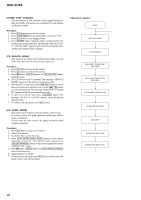
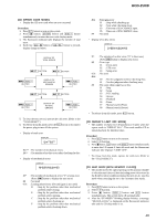
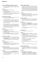
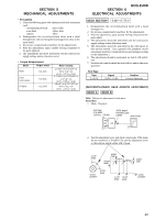
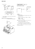
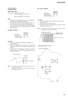
HCD-ZUX9 CD SECTION [TEST DISC LIST] Use the following test disc on test mode. • CD: YEDS-18 (PART No. 3-702-101-01) or PATD-012 (PART No. 4-225-203-01) Note: 1. CD Block is basically designed to operate without adjustment. Therefore, check each item in order given. 2. Use YEDS-18 (3-702-101-01) unless otherwise indicated. 3. Use an oscilloscope with more than 10MW impedance. 4. Clean the object lens by an applicator with neutral detergent when the signal level is low than specified value with the following checks. [S-CURVE CHECK] BD91 board TP106 (FE) TP124 (VC) oscilloscope + - [RF LEVEL CHECK] BD91 board TP123 (RFO) TP124 (VC) oscilloscope + - Procedure : 1. Connect an oscilloscope to TP123 (RFO) and TP124 (VC). 2. Turn the power on. 3. Load a disc (YEDS-18) and playback. 4. Confirm that oscilloscope waveform is clear and check if RF signal level is correct or not. Note: Clear RF signal waveform means that the shape "◊" can be clearly distinguished at the center of the waveform. RFMON signal waveform VOLT/DIV: 200 mV TIME/DIV: 500 ns level: 1.3 ± 0.3 Vp-p Procedure : 1. Connect an oscilloscope to TP106 (FE) and TP124 (VC). 2. Turn the power on. 3. Load a disc (YEDS-18) and actuate the focus search. (In consequence of open and close the disc tray, actuate the focus search). 4. Confirm that the oscilloscope waveform (S-curve) is symmetrical between A and B. And confirm peak to peak level within 3 ± 0.5 Vp-p. S-curve waveform symmetry Connecting Location: CD board - BD91 Board (SIDE B) - A within 3 ±0.5Vp-p B TP124 (VC) 28 15 IC401 1 14 Note: • Try to measure several times to make sure than the ratio of A : B or B : A is more than 10 : 7. • Take sweep time as long as possible and light up the brightness to obtain best waveform. TP123 (RFO) 75 76 51 50 IC101 100 1 TP106 (FE) 26 25 33
-
 1
1 -
2
-
3
-
4
-
5
-
6
-
7
-
8
-
9
-
10
-
11
-
12
-
13
-
14
-
15
-
16
-
17
-
18
-
19
-
20
-
21
-
22
-
23
-
24
-
25
-
26
-
27
-
 28
28 -
 29
29 -
 30
30 -
 31
31 -
 32
32 -
 33
33 -
 34
34 -
 35
35 -
 36
36 -
 37
37 -
 38
38 -
39
-
40
-
41
-
42
-
43
-
44
-
45
-
46
-
47
-
48
-
49
-
50
-
51
-
52
-
53
-
54
-
55
-
56
-
57
-
58
-
59
-
60
-
61
-
62
-
63
-
64
-
65
-
66
-
67
-
68
-
69
-
70
-
71
-
72
-
73
-
74
-
75
-
76
-
77
-
78
-
79
-
80
-
81
-
82
-
83
-
84
-
85
-
86
-
87
-
88
-
89
-
90
-
91
-
92
-
93
-
94
-
95
-
96
-
97
-
98
-
99
-
100
-
101
-
102
-
103
-
104
-
105
-
106
-
107
-
108
-
109
-
110
-
111
-
112
-
113
-
114
-
115
-
116
-
117
-
118
 |
 |
