Sony HCD-ZUX9 Service Manual - Page 81
Sony HCD-ZUX9 Manual
 |
View all Sony HCD-ZUX9 manuals
Add to My Manuals
Save this manual to your list of manuals |
Page 81 highlights
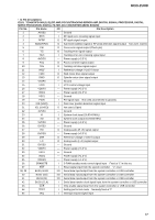
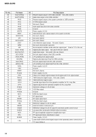
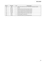
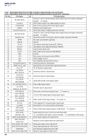
HCD-ZUX9 Pin No. Pin Name I/O 39 TBL-SENSE I 40 E-3 I 41 E-2 I 42 E-1 I 43 TMF O 44 TMR O 45 LMF O 46 LMR O 47 UNDER VOLTAGE I 48 OVER VOLTAGE I 49 SPEED FAN-HI O 50 FR_RELAY O 51 STK-MUTE O 52 H/P-MUTE O 53 PROTECTOR I 54 H/P_DETECT I 55 LINE-MUTE O 56 M61530-DATA O 57 M61530-CLK O EFFECTOR_SOURCE 58 O _SELECT2 EFFECTOR_SOURCE 59 O _SELECT1 60 EFFECTOR_SELECT O 61 EFFECTOR_CTRL3 O 62 VCC - 63 EFFECTOR_CTRL2 O 64 VSS - 65 EFFECTOR_S3 O 66 EFFECTOR_S2 O 67 EFFECTOR_S1 O 68 EFFECTOR_S0 O 69 EFFECTOR_CTRL1 O 70 M61537-DATA O 71 M61537-CLK O [REC-MUTE]/ 72 O SURR_RELAY 73 DISPLAY-KEY I 74 POWER-KEY I [TC-MUTE]/ 75 I ML2252_BUSY2 [TC-RELAY]/ 76 O I/O_EXP_DATA-OUT [REC-BIAS] 77 O I/O_EXP_PWR-CTRL [B-TRIG] 78 O I/O_EXP_LATCH [CAPM-CNT]/ 79 O I/O_EXP_CLK Pin Description Disc tray position detection signal input from CDM Disc tray status detection signal input from CDM Disc tray status detection signal input from CDM Disc tray status detection signal input from CDM CDM turning motor control signal output CDM turning motor control signal output CDM loading motor control signal output CDM loading motor control signal output Under-voltage protection detection input Over-voltage protection detection input Fan speed control signal output "L": high speed Relay drive signal output for the front speakers "H": relay on Power amplifier on/off control signal output "H": amplifier on Headphone muting on/off control signal "L": muting on Speaker protect detection signal input from speaker protect circuit "L": protector on Headphone connection detection signal input "H": headphone connected Line muting on/off control signal "H": muting on Serial data output to electric volume, M61530FP Serial data transfer clock signal output to electric volume, M61530FP Control signal 2 output to source selector at the effector circuitry Control signal 1 output to source selector at the effector circuitry Effector circuity bypass control signal output "H": bypass Effector mode control signal 3 output Power supply (+3.3V) Effector mode control signal 2 output Ground Effector circuitry delay time selection bit 3 output Effector circuitry delay time selection bit 2 output Effector circuitry delay time selection bit 1 output Effector circuitry delay time selection bit 0 output Effector mode control signal 1 output Serial data output to REC/PB AMP, M61537FP Serial data transfer clock signal output to REC/PB AMP, M61537FP Relay drive signal output for the speakers "H": relay on DISPLAY key press detection Interrupt input POWER key press detection Interrupt input Channel 2 playback status signal from digital synthesizer ML2252 "H": Playback stop Serial data output signal to I/O expander Power on/off control signal to I/O expander Serial data clock signal to I/O expander Serial data latch signal to I/O expander 81
-
 1
1 -
2
-
3
-
4
-
5
-
6
-
7
-
8
-
9
-
10
-
11
-
12
-
13
-
14
-
15
-
16
-
17
-
18
-
19
-
20
-
21
-
22
-
23
-
24
-
25
-
26
-
27
-
28
-
29
-
30
-
31
-
32
-
33
-
34
-
35
-
36
-
37
-
38
-
39
-
40
-
41
-
42
-
43
-
44
-
45
-
46
-
47
-
48
-
49
-
50
-
51
-
52
-
53
-
54
-
55
-
56
-
57
-
58
-
59
-
60
-
61
-
62
-
63
-
64
-
65
-
66
-
67
-
68
-
69
-
70
-
71
-
72
-
73
-
74
-
75
-
 76
76 -
 77
77 -
 78
78 -
 79
79 -
 80
80 -
 81
81 -
 82
82 -
 83
83 -
 84
84 -
 85
85 -
 86
86 -
87
-
88
-
89
-
90
-
91
-
92
-
93
-
94
-
95
-
96
-
97
-
98
-
99
-
100
-
101
-
102
-
103
-
104
-
105
-
106
-
107
-
108
-
109
-
110
-
111
-
112
-
113
-
114
-
115
-
116
-
117
-
118
 |
 |
