Sony HCD-ZUX9 Service Manual - Page 32
Tuner,
 |
View all Sony HCD-ZUX9 manuals
Add to My Manuals
Save this manual to your list of manuals |
Page 32 highlights
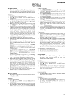
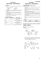
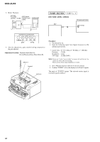
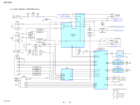
HCD-ZUX9 3. Mode: Playback test tape P-4-A100 JACK board (10 kHz, −10 dB) PHONES jack oscilloscope (J904) VH set TUNER SECTION 0 dB = 1 µV [FM TUNE LEVEL CHECK] FM signal generator SET OUT (75 Ω) waveform of oscilloscope in phase 45 90 135 180 good wrong 4. After the adjustments, apply suitable locking compound to the pats adjusted. Adjustment Location: Playback Head (Deck A). Record/Playback/Erase Head (Deck B). DECK A forward DECK B Procedure: 1. Turn the power on. 2. Input the following signal from Signal Generator to FM antenna input directly. * Carrier Freq : A = 87.5 MHz, B = 98 MHz, C = 108 MHz Deviation : 75 kHz Modulation : 1 kHz ANT input : 35 dBu (EMF) Note: Please use 75 ohm "coaxial cable" to connect SG and the set. You cannot use video cable for checking. Please use SG whose output impedance is 75 ohm. 3. Set to FM tuner function and tune A, B and C signals. 4. Confirm "TUNED" is lit on the display for A, B and C signals. The mark of "TUNED" means "The selected station signal is received in good condition." 32
-
 1
1 -
2
-
3
-
4
-
5
-
6
-
7
-
8
-
9
-
10
-
11
-
12
-
13
-
14
-
15
-
16
-
17
-
18
-
19
-
20
-
21
-
22
-
23
-
24
-
25
-
26
-
 27
27 -
 28
28 -
 29
29 -
 30
30 -
 31
31 -
 32
32 -
 33
33 -
 34
34 -
 35
35 -
 36
36 -
 37
37 -
38
-
39
-
40
-
41
-
42
-
43
-
44
-
45
-
46
-
47
-
48
-
49
-
50
-
51
-
52
-
53
-
54
-
55
-
56
-
57
-
58
-
59
-
60
-
61
-
62
-
63
-
64
-
65
-
66
-
67
-
68
-
69
-
70
-
71
-
72
-
73
-
74
-
75
-
76
-
77
-
78
-
79
-
80
-
81
-
82
-
83
-
84
-
85
-
86
-
87
-
88
-
89
-
90
-
91
-
92
-
93
-
94
-
95
-
96
-
97
-
98
-
99
-
100
-
101
-
102
-
103
-
104
-
105
-
106
-
107
-
108
-
109
-
110
-
111
-
112
-
113
-
114
-
115
-
116
-
117
-
118
 |
 |
