Sony HCD-ZUX9 Service Manual - Page 31
Hcd-zux9, Mechanical, Adjustments, Electrical
 |
View all Sony HCD-ZUX9 manuals
Add to My Manuals
Save this manual to your list of manuals |
Page 31 highlights
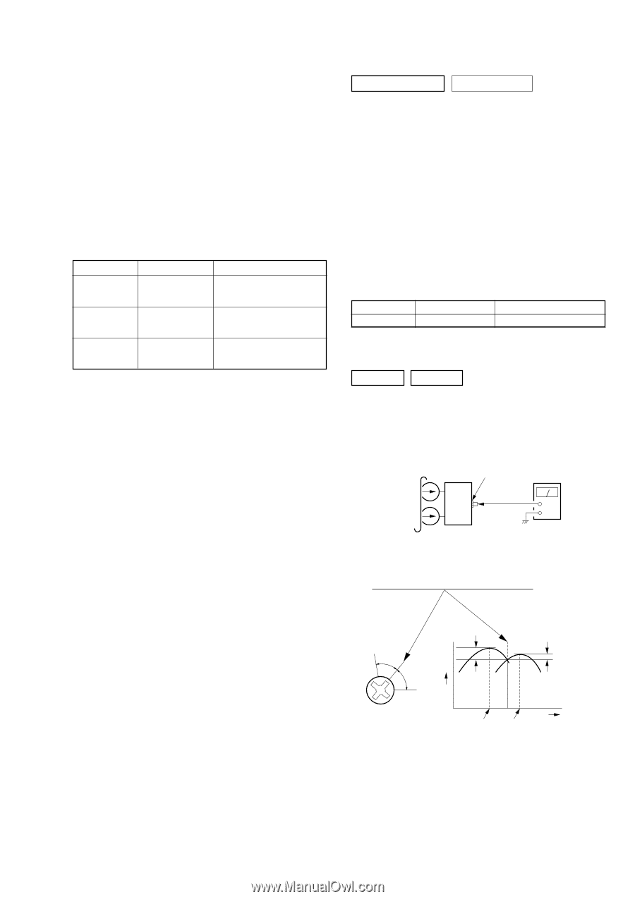
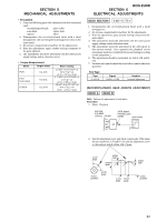
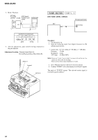
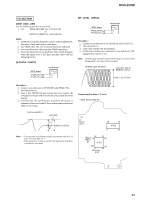
SECTION 5 MECHANICAL ADJUSTMENTS • Precaution 1. Clean the following parts with a denatured alcohol-moistened swab : record/playback heads pinch roller erase head rubber belts capstan idlers 2. Demagnetize the record/playback head with a head demagnetizer. (Do not bring the head magnetizer close to the erase head.) 3. Do not use a magnetized screwdriver for the adjustments. 4. After the adjustments, apply suitable locking compound to the parts adjusted. 5. The adjustments should be performed with the rated power supply voltage unless otherwise noted. • Torque Measurement Mode Torque meter FWD CQ-102C FWD back tension CQ-102C FF/REW CQ-201B Meter reading 2.9 mN • m to 6.9 mN • m 30 to 70 g • cm (0.42 - 0.97 oz • inch) 0.15 mN • m to 0.59 mN • m 2 to 6 g • cm (0.03 - 0.08 oz • inch) 4.8 mN • m to 16.7 mN • m 49 to 170 g • cm (0.68 - 2.36 oz • inch) HCD-ZUX9 SECTION 6 ELECTRICAL ADJUSTMENTS DECK SECTION 0 dB = 0.775 V 1. Demagnetize the record/playback head with a head demagnetizer. 2. Do not use a magnetized screwdriver for the adjustments. 3. After the adjustments, apply suitable locking compound to the parts adjust. 4. The adjustments should be performed with the rated power supply voltage unless otherwise noted. 5. The adjustments should be performed in the order given in this service manual. (As a general rule, playback circuit adjustment should be completed before performing recording circuit adjustment.) 6. The adjustments should be performed for both L-CH and RCH. 7. Switches and controls should be set as follows unless otherwise specified. • Test Tape Tape P-4-A100 Signal 10 kHz, -10 dB Used for Azimuth Adjustment [RECORD/PLAYBACK HEAD AZIMUTH ADJUSTMENT] DECK A DECK B Note: Perform this adjustments for both decks Procedure: 1. Mode: Playback test tape P-4-A100 (10 kHz, −10 dB) JACK board PHONES jack (J904) level meter set + - 2. Turn the adjustment screw and check output peaks. If the peaks do not match for L-CH and R-CH, turn the adjustment screw so that outputs match within 1dB of peak. L-CH peak within 1dB output level screw position R-CH peak L-CH R-CH peak peak within 1dB screw position 31
-
 1
1 -
2
-
3
-
4
-
5
-
6
-
7
-
8
-
9
-
10
-
11
-
12
-
13
-
14
-
15
-
16
-
17
-
18
-
19
-
20
-
21
-
22
-
23
-
24
-
25
-
 26
26 -
 27
27 -
 28
28 -
 29
29 -
 30
30 -
 31
31 -
 32
32 -
 33
33 -
 34
34 -
 35
35 -
 36
36 -
37
-
38
-
39
-
40
-
41
-
42
-
43
-
44
-
45
-
46
-
47
-
48
-
49
-
50
-
51
-
52
-
53
-
54
-
55
-
56
-
57
-
58
-
59
-
60
-
61
-
62
-
63
-
64
-
65
-
66
-
67
-
68
-
69
-
70
-
71
-
72
-
73
-
74
-
75
-
76
-
77
-
78
-
79
-
80
-
81
-
82
-
83
-
84
-
85
-
86
-
87
-
88
-
89
-
90
-
91
-
92
-
93
-
94
-
95
-
96
-
97
-
98
-
99
-
100
-
101
-
102
-
103
-
104
-
105
-
106
-
107
-
108
-
109
-
110
-
111
-
112
-
113
-
114
-
115
-
116
-
117
-
118
 |
 |