Sony HDCU-4300 Operation Guide - Page 6
IP transmission connection example
 |
View all Sony HDCU-4300 manuals
Add to My Manuals
Save this manual to your list of manuals |
Page 6 highlights
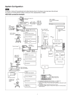
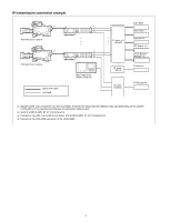
IP transmission connection example a) c) c) d) HDCU4300 b) HDC4300 Color Camera HDC4300 Color Camera a) c) c) d) HDCU4300 b) MSU-1000 series Master Setup Unit Optical fiber cable LAN cable IP switch × 2 10G/25G IP switch 10G/1G Audio Mixer Multi Viewer Video Server PTP Master × 2 IP Live System Manager × 2 IP Intercom IP switch 100M/1G IP Tally System a) Signal transfer over a maximum of 2 km is possible. However, the actual transfer distance may vary depending on the system configuration of the cameras and the type of optical fiber cables used. b) Install the HKCU-4001 ST 2110 Interface Kit. c) Connect to the LAN-1 and LAN-2 connectors of the HKCU-4001 ST 2110 Interface Kit. d) Connect to the LAN-COM connector of the HDCU4300. 6
-
 1
1 -
 2
2 -
 3
3 -
 4
4 -
 5
5 -
 6
6 -
 7
7 -
 8
8 -
 9
9 -
 10
10 -
 11
11 -
 12
12 -
13
-
14
-
15
-
16
-
17
-
18
-
19
-
20
-
21
-
22
-
23
-
24
-
25
-
26
-
27
-
28
-
29
-
30
-
31
-
32
-
33
-
34
-
35
-
36
-
37
-
38
-
39
-
40
-
41
-
42
-
43
-
44
-
45
-
46
-
47
-
48
-
49
-
50
-
51
-
52
-
53
-
54
-
55
-
56
-
57
-
58
-
59
-
60
-
61
-
62
-
63
-
64
-
65
-
66
-
67
 |
 |

6
IP transmission connection example
a)
Signal transfer over a maximum of 2 km is possible. However, the actual transfer distance may vary depending on the system
configuration of the cameras and the type of optical fiber cables used.
b)
Install the HKCU-4001 ST 2110 Interface Kit.
c)
Connect to the LAN-1 and LAN-2 connectors of the HKCU-4001 ST 2110 Interface Kit.
d)
Connect to the LAN-COM connector of the HDCU4300.
HDCU4300
b
)
MSU-1000 series
Master Setup Unit
IP switch
100M/1G
Audio Mixer
Optical fiber cable
LAN cable
Multi Viewer
Video Server
PTP Master × 2
IP Live System
Manager × 2
IP Intercom
IP Tally System
IP switch
10G/1G
IP switch × 2
10G/25G
HDCU4300
b
)
c)
c)
d)
c)
c)
d)
HDC4300 Color Camera
HDC4300 Color Camera
a)
a)