Sony HDCU-4300 Operation Guide - Page 7
Location and Function of Parts, Front Panel
 |
View all Sony HDCU-4300 manuals
Add to My Manuals
Save this manual to your list of manuals |
Page 7 highlights
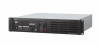
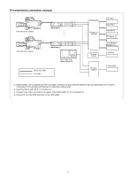
Location and Function of Parts Front Panel 3 124 56 7 89 0 qa qs qd qf a Red tally indicator Lights in red when this unit receives a red tally signal. You can attach the supplied number plate here. b Yellow tally indicator Lights in yellow when this unit receives a yellow tally signal. c Green tally indicator Lights in green when this unit receives a green tally signal. d CCU number display Displays the camera number set in the CCU menu. e NMI STATUS indicator or NETWORK indicator • NMI STATUS indicator (when HKCU-IP43F is installed) Displays the NMI-LAN status. Green: Normal status Flashing green: Network synchronization in progress Off: SFP+ module is not installed. Disconnected from IP Live System Manager. Connection with IP Live System Manager in progress Flashing red: Not locked to network sync signal. Signal reception is unavailable. • NETWORK indicator (when HKCU-4001 is installed) Displays the GENLOCK status of the network. Low-speed flashing: PTP master not detected High-speed flashing: Genlock initiated Lit: Genlock achieved Not lit: Network genlock setting disabled f Status display indicator REF IN (green): Indicates presence of REFERENCE input signal. UNLOCK (Red): Not locked to the REFERENCE input signal. NETWORK or RCP/MSU (when HKCU-4001 is installed): Displays the status when there is a network system connection. On: When CNS MODE on the page in the NETWORK menu is set to either BRIDGE or MCS, this indicates that external control equipment (MSU-1000/1500 Master Setup Unit, RCP-3000/ 1000 series Remote Control Panel, or other equipment) is connected. Flashing: When CNS MODE on the page in the NETWORK menu is set to either BRIDGE or MCS, this indicates that the unit cannot connect correctly with external control equipment (MSU-1000/ 1500 Master Setup Unit, RCP-3000/1000 series Remote Control Panel, or other equipment). Off: When CNS MODE on the page in the NETWORK menu is set to either BRIDGE or MCS, this indicates that a LAN cable is not connected or that the network system connection settings have not been configured. When CNS MODE on the page in the NETWORK menu is set to LEGACY, this remains turned off. COM ERROR (Red): Communication with the camera or external control equipment (such as the RCP-3000/1000 series Remote Control Panel) is not possible. FAN STOP (Red): The fan is stopped. 7
-
 1
1 -
 2
2 -
 3
3 -
 4
4 -
 5
5 -
 6
6 -
 7
7 -
 8
8 -
 9
9 -
 10
10 -
 11
11 -
 12
12 -
13
-
14
-
15
-
16
-
17
-
18
-
19
-
20
-
21
-
22
-
23
-
24
-
25
-
26
-
27
-
28
-
29
-
30
-
31
-
32
-
33
-
34
-
35
-
36
-
37
-
38
-
39
-
40
-
41
-
42
-
43
-
44
-
45
-
46
-
47
-
48
-
49
-
50
-
51
-
52
-
53
-
54
-
55
-
56
-
57
-
58
-
59
-
60
-
61
-
62
-
63
-
64
-
65
-
66
-
67
 |
 |
