Sony RM-BR300 Operating Instructions - Page 11
Connecting Multiple Cameras Equipped with VISCA RS-422 Connector, To assign camera addresses
 |
View all Sony RM-BR300 manuals
Add to My Manuals
Save this manual to your list of manuals |
Page 11 highlights
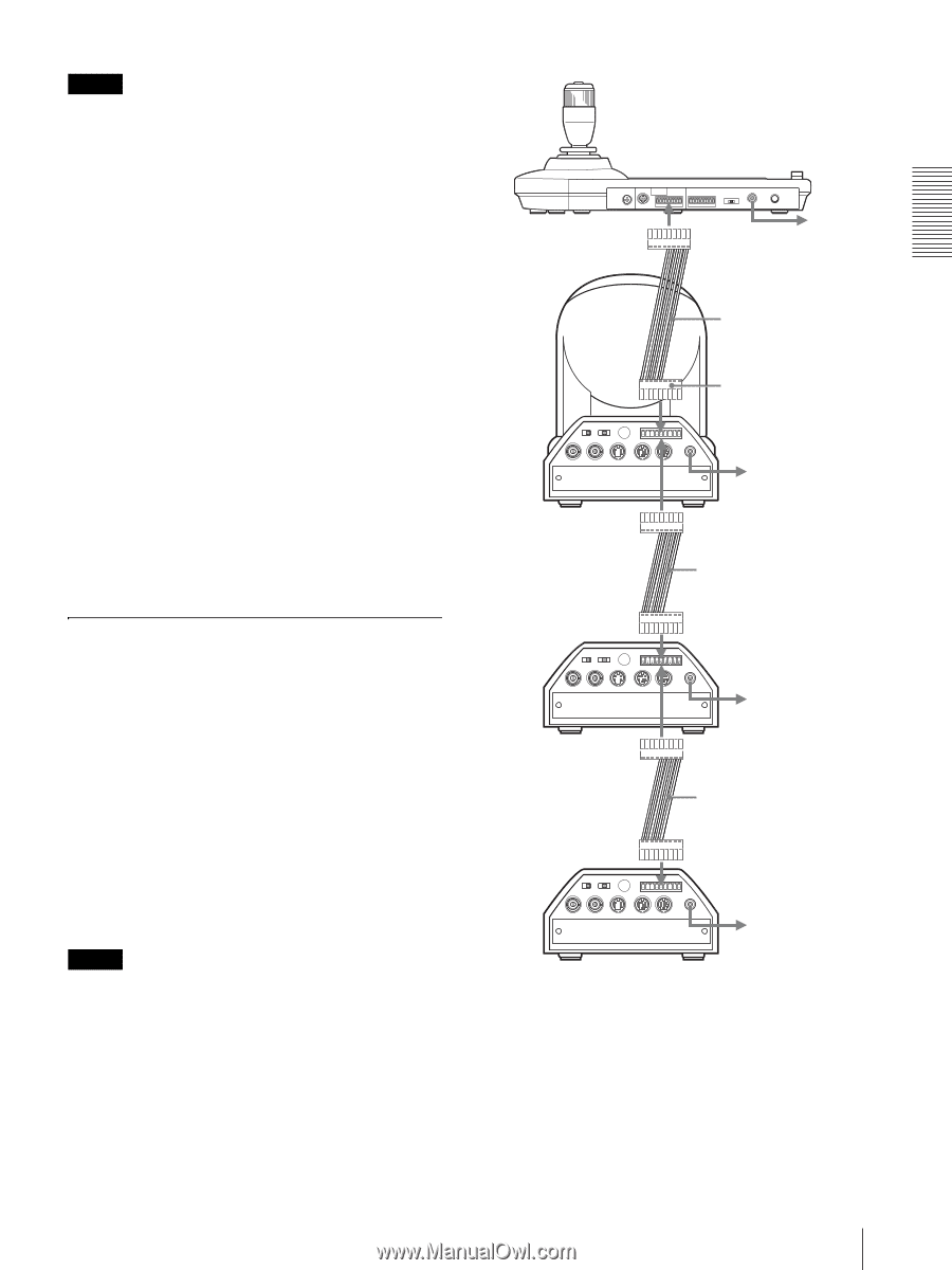
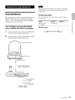
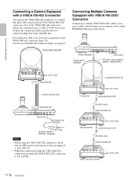
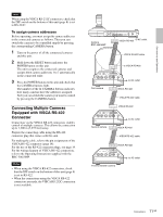
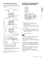
Connections and Operations Note When using the VISCA RS-232C connectors, check that the DIP switch on the bottom of this unit (page 8) is set to RS-232C. To assign camera addresses Before operating, you must assign the camera addresses to the connected cameras as follows. Then you can switch the camera to be controlled simply by pressing the corresponding CAMERA button. 1 Turn on the power of all the connetcted cameras and this unit. 2 Hold down the RESET button and press the POWER button on this unit. The unit recognizes the connected cameras and assigns them camera addresses 1 to 7 automatically in the connected order. 3 Press the POWER button on this unit and check that the CAMERA buttons light. The number of the lit CAMERA buttons indicates how many cameras have the addresses assigned. Now you can switch the camera you want to control by pressing the CAMERA button. Connecting Multiple Cameras Equipped with VISCA RS-422 Connector Connection via the VISCA RS-422 connectors enables control of multiple cameras. This allows the connection up to 1,200 m (3,937 feet) away. Prepare the connecting cable using the RS-422 connector plug that comes with this unit. For making the cable, refer to the pin assignments of the VISCA RS-422 connector (page 18). For the use of the RS-422 connector plugs, see page 19. For the wiring diagram of VISCA RS-422 connection, refer to the Operating Instructions supplied with the BRC-300/300P. Notes • When using the VISCA RS-422 connectors, check that the DIP switch on the bottom of this unit (page 8) is set to RS-422. • When the connections using the VISCA RS-422 connectors are made, the VISCA RS-232C connection is not available. Camera BRC-300/300P VISCA RS-422 to AC outlet VISCA RS-422 cable to VISCA RS-422 R 1 2 3 OFF ON 75 IR SELECT 1 2 3 4 5 6 7 8 9 VISCA RS-422 ! EXT SYNC IN VIDEO S VIDEO IN VISCA RS-232C OUT DC IN 12V to AC outlet First camera VISCA RS-422 VISCA RS-422 cable VISCA RS-422 R 1 2 3 OFF ON 75 IR SELECT 1 2 3 4 5 6 7 8 9 VISCA RS-422 ! EXT SYNC IN VIDEO S VIDEO IN VISCA RS-232C OUT DC IN 12V to AC outlet Second camera VISCA RS-422 VISCA RS-422 cable VISCA RS-422 R 1 2 3 OFF ON 75 IR SELECT 1 2 3 4 5 6 7 8 9 VISCA RS-422 ! EXT SYNC IN VIDEO S VIDEO IN VISCA RS-232C OUT DC IN 12V to AC outlet Third to Seventh camera 11 Connections GB
-
 1
1 -
2
-
3
-
4
-
5
-
 6
6 -
 7
7 -
 8
8 -
 9
9 -
 10
10 -
 11
11 -
 12
12 -
 13
13 -
 14
14 -
 15
15 -
 16
16 -
17
-
18
-
19
-
20
-
21
-
22
-
23
-
24
-
25
-
26
-
27
-
28
-
29
-
30
-
31
-
32
-
33
-
34
-
35
-
36
-
37
-
38
-
39
-
40
-
41
-
42
-
43
-
44
-
45
-
46
-
47
-
48
-
49
-
50
-
51
-
52
-
53
-
54
-
55
-
56
-
57
-
58
-
59
-
60
-
61
-
62
-
63
-
64
-
65
-
66
-
67
-
68
-
69
-
70
-
71
-
72
-
73
-
74
-
75
-
76
-
77
-
78
-
79
-
80
 |
 |