Sony RM-BR300 Operating Instructions - Page 8
Available Functions for Sony VISCA Cameras, Switch 1 RS-232C/RS-422 selector - camera controller
 |
View all Sony RM-BR300 manuals
Add to My Manuals
Save this manual to your list of manuals |
Page 8 highlights
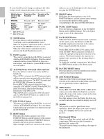
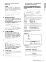
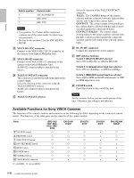
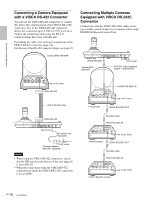
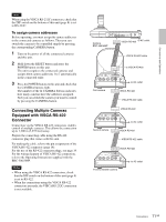
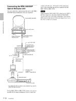
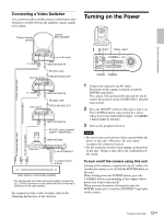
Overview Switch position 5 6 7 Camera mode SNC-RZ30N/RZ30P BRC-H700 BRC-Z700 Notes • Use position 1 to 7 when all the connected cameras are of the same model. In other cases, use position 0. • Be sure to use position 5 for the SNC-RZ30N/ RZ30P. V VISCA RS-232C connector Connect to the VISCA RS-232C IN connector of the camera or the Optical Multiplex Unit. W VISCA RS-422 connector Connect to the VISCA RS-422 connector of the camera or the Optical Multiplex Unit. An RS-422 connector plug is attached at the factory. X TALLY/CONTACT connector This connector is used for the tally lamp input or the contact output. Select the function of the connector using the TALLY/CONTACT selector. An RS-422 connector plug is attached at the factory. Y TALLY/CONTACT selector Select the function of the TALLY/CONTACT connector. TALLY: The CAMERA button of the camera selected with the connected switcher lights in blue and the tally lamp of this camera lights. CONTACT: The contact output corresponding to the camera address selected with this unit is shortcircuited against the connected switcher. CONTACT (TALLY): The contact output corresponding to the camera address selected with this unit is short-circuited against the connected switcher and the tally lamp of the selected camera lights. wh DC IN 12V connector Connect the supplied AC power adaptor. wj DIP switches (bottom) Switch 1 (RS-232C/RS-422 selector) Set to ON for RS-422, or OFF for RS-232C. Switch 2 (Communication baud rate selector) Set to ON for 38,400bps, or OFF for 9,600bps. Switch 3 (BRIGHT control function selector) Set to ON for IRIS and GAIN adjustments, or OFF for IRIS adjustment only. wk ON/OFF switch Press this switch to turn on/off this unit. Note Set the switches before you turn on the power of this unit. Otherwise, the setting is not effective. Available Functions for Sony VISCA Cameras The functions of the controls, buttons and connectors in the following list differ depending on the connected camera model. The functions of the other parts are the same for all the camera models. Parts B VALUE/R control C BRIGHT/B control G ONE PUSH AF button L PAN-TILT RESET button N MENU button R POWER button S CAMERA buttons W VISCA RS-422 connector a: available, ×: not available BRC-300/ 300P, BRCH700, BRC- Z700 a a a a a a a a EVI-D100/ D100P a a a a a a a × EVI-D70/ D70P a a a a a a a a EVI-D30/ D30P SNC-RZ30N/ RZ30P × a × a × a a × a × a × a × × × 8 GB Location and Function of Parts
-
 1
1 -
2
-
 3
3 -
 4
4 -
 5
5 -
 6
6 -
 7
7 -
 8
8 -
 9
9 -
 10
10 -
 11
11 -
 12
12 -
 13
13 -
14
-
15
-
16
-
17
-
18
-
19
-
20
-
21
-
22
-
23
-
24
-
25
-
26
-
27
-
28
-
29
-
30
-
31
-
32
-
33
-
34
-
35
-
36
-
37
-
38
-
39
-
40
-
41
-
42
-
43
-
44
-
45
-
46
-
47
-
48
-
49
-
50
-
51
-
52
-
53
-
54
-
55
-
56
-
57
-
58
-
59
-
60
-
61
-
62
-
63
-
64
-
65
-
66
-
67
-
68
-
69
-
70
-
71
-
72
-
73
-
74
-
75
-
76
-
77
-
78
-
79
-
80
 |
 |