Sony SDM-M51D Operating Instructions (primary manual) - Page 6
Rear of the LCD display - power cord
 |
View all Sony SDM-M51D manuals
Add to My Manuals
Save this manual to your list of manuals |
Page 6 highlights
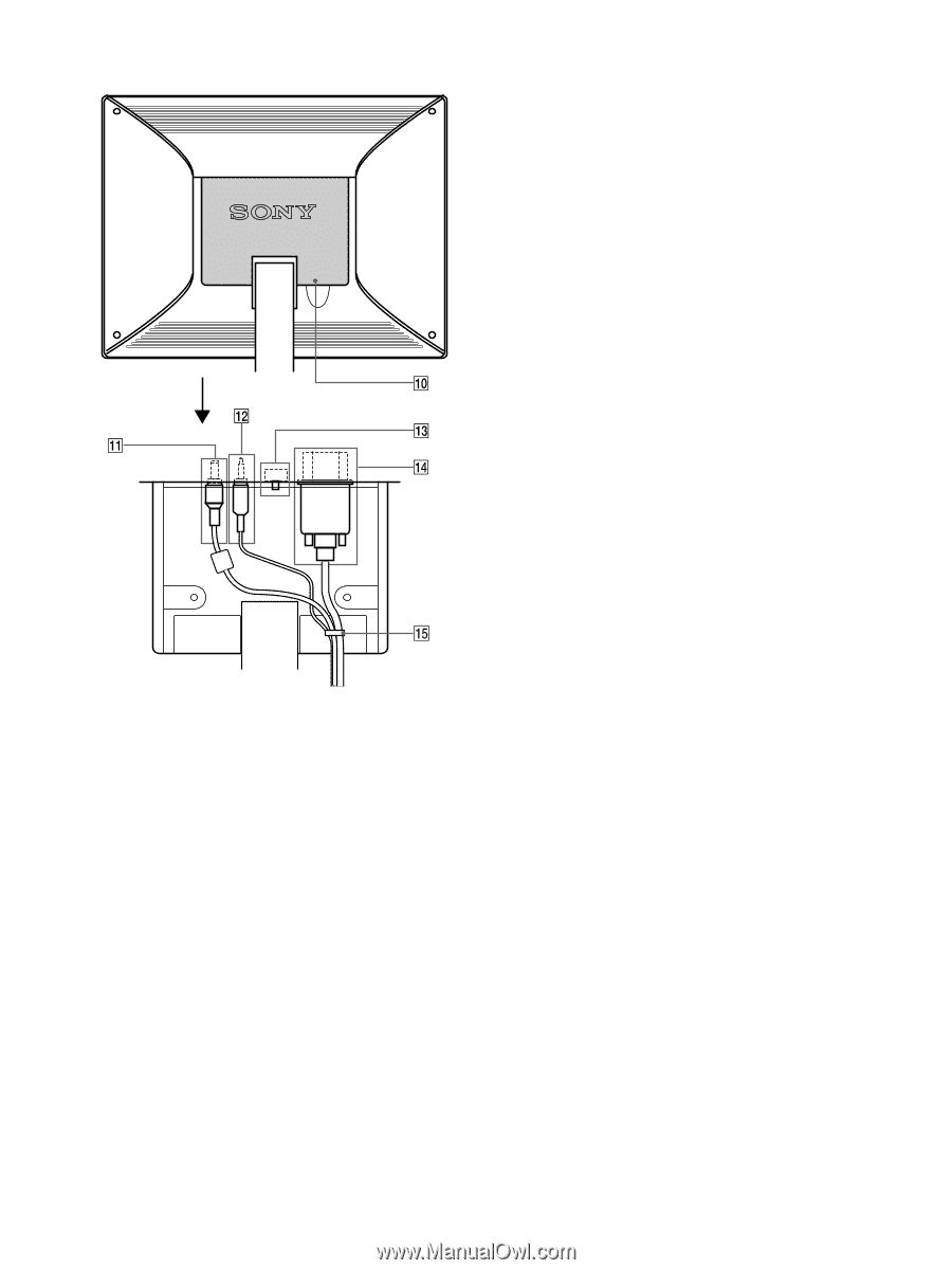
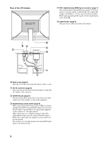
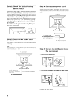
Rear of the LCD display OPEN qf DVI-I (digital/analog RGB) input connector (page 7) This connector inputs analog RGB video signals (0.700 Vp-p, positive) with sync signals or digital RGB video signals that comply with DVI Rev. 1.0. You can switch between digital RGB signals and analog RGB signals with the digital/analog select switch qd. qg Cable holder (page 8) This part secures cables and cords to the monitor. 0 Back cover (page 8) Open this cover when you connect/disconnect cables or cords. qa DC IN connector (page 8) This connector provides DC power to the display. Connect the AC adapter to this connector. qs AUDIO IN jack (page 8) This jack inputs audio signals when connecting to the audio output jack of the computer or other audio equipment. qd Digital/analog select switch (page 8) When connecting the DVI-I input connector qf to a computer equipped with an HD15 (analog RGB) output connector using the DVI-HD15 (analog RGB) video signal cable (supplied), set this switch to A - the right position. When connecting it to a computer equipped with a DVI (digital RGB) output connector using a DVI-DVI (digital RGB) video signal cable (not supplied), set this switch to D - the left position. The switch is set to the right position (for analog RGB signal input) as the default setting. 6
-
 1
1 -
 2
2 -
 3
3 -
 4
4 -
 5
5 -
 6
6 -
 7
7 -
 8
8 -
 9
9 -
 10
10 -
 11
11 -
 12
12 -
13
-
14
-
15
-
16
-
17
-
18
-
19
-
20
-
21
-
22
-
23
-
24
-
25
-
26
-
27
-
28
-
29
-
30
-
31
-
32
-
33
-
34
-
35
-
36
-
37
-
38
-
39
-
40
-
41
-
42
-
43
-
44
-
45
-
46
-
47
-
48
-
49
-
50
-
51
-
52
-
53
-
54
-
55
-
56
-
57
-
58
-
59
-
60
-
61
-
62
-
63
-
64
-
65
-
66
-
67
-
68
-
69
-
70
-
71
-
72
-
73
-
74
-
75
-
76
-
77
-
78
-
79
-
80
-
81
-
82
-
83
-
84
-
85
-
86
-
87
-
88
-
89
-
90
-
91
-
92
-
93
-
94
-
95
-
96
-
97
-
98
-
99
-
100
-
101
-
102
-
103
-
104
 |
 |