Sony STR-DG800 Operating Instructions - Page 25
Hooking up a TV monitor, Getting Started, Notes
 |
UPC - 027242683075
View all Sony STR-DG800 manuals
Add to My Manuals
Save this manual to your list of manuals |
Page 25 highlights
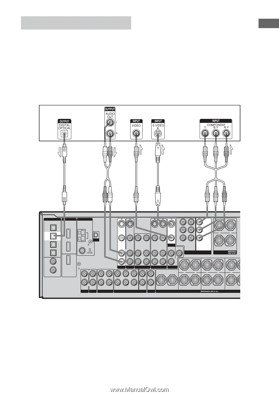
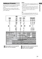
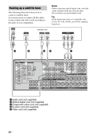
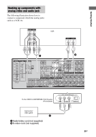
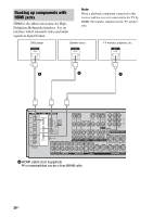
Getting Started Hooking up a TV monitor The image from a visual component connected to this receiver can be displayed on a TV screen. It is not necessary to connect all the cables. Connect video cords according to the jacks of your components. Notes • Connect image display components such as a TV monitor or a projector to the MONITOR OUT jack on the receiver. • Turn on the receiver when the video and audio of a playback component are being output to a TV via the receiver. If the power supply of the receiver is not turned on, neither video nor audio is transmitted. Tip You can watch the selected input image when you connect the MONITOR OUT jack to a TV monitor. TV monitor A B ED C DIGITAL OPTICAL VIDEO 1 IN TV/SAT IN MD/ TAPE IN MD/ TAPE OUT HDMI ANTENNA ASSIGNABLE DVD IN TV/ SAT IN AM XM Y S-VIDEO S-VIDEO IN IN S-VIDEO OUT S-VIDEO IN S-VIDEO OUT PB/CB /B-Y PR/CR /R-Y VIDEO IN VIDEO IN AUDIO IN AUDIO IN L VIDEO OUT VIDEO IN AUDIO OUT AUDIO IN L VIDEO OUT VIDEO IN AUDIO OUT AUDIO IN L VIDEO OUT MONITOR TV/SAT IN DVD MONITOR IN OUT L SUR SUB WOOFER ASSIGNABLE COMPONENT VIDEO L + - R FRONT B SPEAKERS DVD IN SA-CD/ CD IN COAXIAL ASSIGNABLE (INPUT ONLY) MONITOR OUT SIGNAL GND L R R R R TV/SAT DVD VIDEO 2 VIDEO 1 PRE OUT L L L L + - + - CENTER L R IN IN PHONO SA-CD/CD R OUT IN MD/TAPE R R SUR FRONT SURROUND BACK MULTI CH IN SUB WOOFER R OUT ZONE 2 CENTER R SURROUND BACK SPEAKERS L + - R SURROUND L + R FRONT A A Optical digital cord (not supplied) B Audio cord (not supplied) C Component video cord (not supplied) D S-video cord (not supplied) E Video cord (not supplied) 25US
-
 1
1 -
2
-
3
-
4
-
5
-
6
-
7
-
8
-
9
-
10
-
11
-
12
-
13
-
14
-
15
-
16
-
17
-
18
-
19
-
 20
20 -
 21
21 -
 22
22 -
 23
23 -
 24
24 -
 25
25 -
 26
26 -
 27
27 -
 28
28 -
 29
29 -
 30
30 -
31
-
32
-
33
-
34
-
35
-
36
-
37
-
38
-
39
-
40
-
41
-
42
-
43
-
44
-
45
-
46
-
47
-
48
-
49
-
50
-
51
-
52
-
53
-
54
-
55
-
56
-
57
-
58
-
59
-
60
-
61
-
62
-
63
-
64
-
65
-
66
-
67
-
68
-
69
-
70
-
71
-
72
-
73
-
74
-
75
-
76
-
77
-
78
-
79
-
80
-
81
-
82
-
83
-
84
-
85
-
86
-
87
-
88
-
89
-
90
-
91
-
92
-
93
-
94
-
95
-
96
-
97
-
98
-
99
-
100
 |
 |