Sony UP-897MD User Instructions - Page 32
Rear Panel, AC IN connector - parts
 |
View all Sony UP-897MD manuals
Add to My Manuals
Save this manual to your list of manuals |
Page 32 highlights
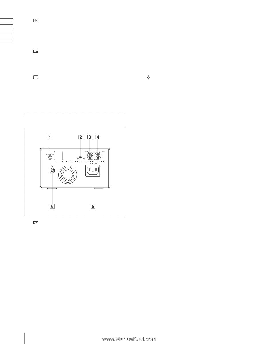
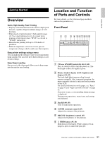
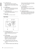
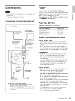
Getting Started G COPY button (43) Prints another copy of the previous printout. You can make only one copy each time you press this button regardless of the print quantity set using the menu. H PRINT button Prints the image currently displayed on the video monitor. The image displayed when you press the PRINT button is stored in memory. I OPEN button (34, 43) Press to open the paper door. While a print job is in progress, press to cancel the print job. J Paper cutter Cuts the paper as each image is printed. Rear Panel Connect to the video input connector of the video monitor. The output signal depends on the setting of the "VIDEO" item of the menu. E - AC IN connector Use a proper power cord for your local power supply (not supplied). Refer to "Warning on power connection" on page 29 and "Warning on power connection for medical use" on page 29. F Equipotential terminal Used to connect to the equipotential plug to bring the various parts of a system to the same potential. Refer to "Important safeguards/notices for use in the medical environments" on page 28. A REMOTE connector (33) Connects the RM-91 remote control unit or the foot switch for controlling print operation from a distance. B 75 Ω select switch ON: When nothing is connected to the VIDEO OUT connector, set the switch to this position. OFF: When a video monitor or other video equipment is connected to the VIDEO OUT connector, set the switch to this position. C t VIDEO IN (input) connector (BNC type) Connect to the video output connector of the video equipment. D T VIDEO OUT (output) connector (BNC type) 32 Location and Function of Parts and Controls
-
 1
1 -
2
-
3
-
4
-
5
-
6
-
7
-
8
-
9
-
10
-
11
-
12
-
13
-
14
-
15
-
16
-
17
-
18
-
19
-
20
-
21
-
22
-
23
-
24
-
25
-
26
-
 27
27 -
 28
28 -
 29
29 -
 30
30 -
 31
31 -
 32
32 -
 33
33 -
 34
34 -
 35
35 -
 36
36 -
 37
37 -
38
-
39
-
40
-
41
-
42
-
43
-
44
-
45
-
46
-
47
-
48
-
49
-
50
-
51
-
52
-
53
-
54
-
55
-
56
-
57
-
58
-
59
-
60
-
61
-
62
-
63
-
64
-
65
-
66
-
67
-
68
-
69
-
70
-
71
-
72
-
73
-
74
-
75
-
76
-
77
-
78
-
79
-
80
-
81
-
82
-
83
-
84
-
85
-
86
-
87
-
88
-
89
-
90
-
91
-
92
-
93
-
94
-
95
-
96
-
97
-
98
-
99
-
100
-
101
-
102
-
103
-
104
-
105
-
106
-
107
-
108
-
109
-
110
-
111
-
112
-
113
-
114
-
115
-
116
-
117
-
118
-
119
-
120
-
121
-
122
-
123
-
124
-
125
-
126
-
127
-
128
-
129
-
130
-
131
-
132
-
133
-
134
-
135
-
136
-
137
-
138
-
139
-
140
-
141
-
142
-
143
-
144
-
145
-
146
-
147
-
148
-
149
-
150
-
151
-
152
-
153
-
154
-
155
-
156
-
157
-
158
-
159
-
160
 |
 |