Symantec 10521146 User Guide - Page 12
USB connection, Port groups, The Symantec Network Security 7100 Series appliance communicates with
 |
UPC - 037648268134
View all Symantec 10521146 manuals
Add to My Manuals
Save this manual to your list of manuals |
Page 12 highlights
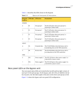
12 In-line Bypass unit features Note: The 4 In-line Bypass unit is supported only for use with the Symantec Network Security 7160 appliance. Figure 1-2 shows the rear panel of the 4 In-line Bypass unit. Figure 1-2 4 In-line Bypass unit 1 - Serial port (unused) 2 - Mgmt USB 3 - Power supply 1 4 - Power supply 2 5 - Port group 0 6 - Port group 1 7 - Port group 2 8 - Port group 3 Each port group includes: Net A, App A, App B, Net B USB connection The Symantec Network Security 7100 Series appliance communicates with the In-line Bypass unit via the USB connection. The appliance sends commands to the bypass unit and also sends a periodic keep-alive signal through the USB connection. Port groups The 2 In-line Bypass unit contains two groups of four ports each, referred to as port groups. The ports in the port group connect to the two network segments and the two interfaces of the appliance in-line pair. The 4 In-line Bypass unit contains four port groups. Figure 1-3 Port group layout Net A App A App B Net B
-
 1
1 -
2
-
3
-
4
-
5
-
6
-
 7
7 -
 8
8 -
 9
9 -
 10
10 -
 11
11 -
 12
12 -
 13
13 -
 14
14 -
 15
15 -
 16
16 -
 17
17 -
18
-
19
-
20
-
21
-
22
-
23
-
24
-
25
-
26
-
27
-
28
-
29
-
30
 |
 |
