Symantec 10521146 User Guide - Page 17
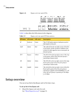
Rear panel LEDs on the bypass unit, Table 1-3, Diagram, location, LED label, LED name, Description
 |
UPC - 037648268134
View all Symantec 10521146 manuals
Add to My Manuals
Save this manual to your list of manuals |
Page 17 highlights
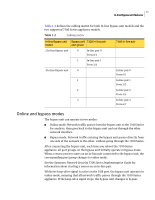
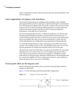
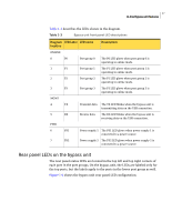
17 In-line Bypass unit features Table 1-3 describes the LEDs shown in the diagram. Table 1-3 Bypass unit front panel LED descriptions Diagram LED label LED name location Description ONLINE 0 P0 1 P1 2 P2 3 P3 MGMT 4 TX 5 RX PWR 6 PS1 7 PS2 Port group 0 Port group 1 Port group 2 Port group 3 The P0 LED glows when port group 0 is operating in online mode. The P1 LED glows when port group 1 is operating in online mode. The P2 LED glows when port group 2 is operating in online mode. The P3 LED glows when port group 3 is operating in online mode. Transmit data The TX LED blinks when the bypass unit is transmitting data on the USB connection. Receive data The RX LED blinks when the bypass unit is receiving data on the USB connection. Power supply 1 The PS1 LED glows when power supply 1 is connected to a power source. Power supply 2 The PS2 LED glows when power supply 2 is connected to a power source. Rear panel LEDs on the bypass unit The rear panel status LEDs are located in the top left and top right corners of each port in the port groups. On the bypass unit, the LEDs are labeled only for the top ports, but the labels apply to the ports in the lower port group as well. Figure 1-6 shows the bypass unit rear panel LED configuration.
-
 1
1 -
2
-
3
-
4
-
5
-
6
-
7
-
8
-
9
-
10
-
11
-
 12
12 -
 13
13 -
 14
14 -
 15
15 -
 16
16 -
 17
17 -
 18
18 -
 19
19 -
 20
20 -
 21
21 -
 22
22 -
23
-
24
-
25
-
26
-
27
-
28
-
29
-
30
 |
 |
