Symantec 10521146 User Guide - Page 21
Cabling port group 0 to the 7120, In-line Bypass unit
 |
UPC - 037648268134
View all Symantec 10521146 manuals
Add to My Manuals
Save this manual to your list of manuals |
Page 21 highlights
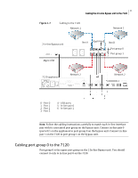
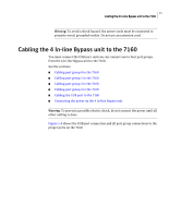
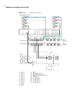
Figure 1-7 21 Cabling the 2 In-line Bypass unit to the 7120 Cabling to the 7120 Network 1 Network 1 2 In-line Bypass unit Mgmt USB Net A AppA AppB Net B Port group 0 Port group 1 7120 appliance Network 2 Network 2 0 - Port 0 1 - Port 1 2 - Port 2 3 - Port 3 4 - USB ports 5 - In-line pair 0 6 - In-line pair 1 Note: Follow the cabling instructions carefully to match each in-line interface pair with its associated port group on the bypass unit. Connect in-line pair 0 (ports 0/1 on the appliance) to port group 0 on the bypass unit. Connect in-line pair 1 on the 7120 to port group 1 on the bypass unit. Cabling port group 0 to the 7120 Port group 0 is the upper port group on the 2 In-line Bypass unit. You should connect it only to in-line pair 0 on the 7120.
-
 1
1 -
2
-
3
-
4
-
5
-
6
-
7
-
8
-
9
-
10
-
11
-
12
-
13
-
14
-
15
-
 16
16 -
 17
17 -
 18
18 -
 19
19 -
 20
20 -
 21
21 -
 22
22 -
 23
23 -
 24
24 -
 25
25 -
 26
26 -
27
-
28
-
29
-
30
 |
 |
