Symantec 10521146 User Guide - Page 16
Auto-negotiation on bypass unit interfaces, Front panel LEDs on the bypass unit
 |
UPC - 037648268134
View all Symantec 10521146 manuals
Add to My Manuals
Save this manual to your list of manuals |
Page 16 highlights
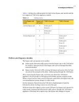
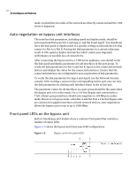
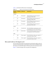
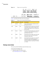
16 In-line Bypass unit features mode, in which the two sides of the network are directly connected and the 7100 Series is bypassed. Auto-negotiation on bypass unit interfaces The interface link parameters, including speed and duplex mode, should be auto-negotiated between Net A and App A, and Net B and App B. You should not force the link speed or duplex mode to a specific setting on network devices that connect to Net A or Net B. Forcing the link parameters to a certain value may result in link speed or duplex mismatches which could cause degraded performance or possible loss of connectivity. After connecting the bypass unit to a 7100 Series appliance, you should verify the link speed and duplex parameters for all interfaces in the port group. To verify the link parameters for Net A and Net B, log on to the connected network devices and display the status for the connected interfaces. Ensure that the connected interfaces are configured for auto-negotiation of link parameters. To verify the link parameters for App A and App B, use the Network Security console. After starting a sensor on the corresponding in-line pair, you can view the link parameters by clicking each interface object in the in-line pair. The parameter values for all interfaces in a port group should be the same when the bypass unit is in online mode. For a 2 In-line Bypass unit connected to a 7120, all port group interfaces should auto-negotiate to 100 Mbps in online mode. However, in bypass mode, when Net A and Net B on a 2 In-line Bypass unit are connected to gigabit interfaces on both network devices, auto-negotiation allows the bypass unit to run at up to 1000 Mbps. Front panel LEDs on the bypass unit Both In-line Bypass unit models share a common front panel that contains a number of status LEDs. Figure 1-5 shows the bypass unit front panel LED configuration. Figure 1-5 Bypass unit front panel LEDs 4 5 0123 6 7
-
 1
1 -
2
-
3
-
4
-
5
-
6
-
7
-
8
-
9
-
10
-
 11
11 -
 12
12 -
 13
13 -
 14
14 -
 15
15 -
 16
16 -
 17
17 -
 18
18 -
 19
19 -
 20
20 -
 21
21 -
22
-
23
-
24
-
25
-
26
-
27
-
28
-
29
-
30
 |
 |
