Symantec 10521146 User Guide - Page 20
Cabling the 2 In-line Bypass unit to the 7120
 |
UPC - 037648268134
View all Symantec 10521146 manuals
Add to My Manuals
Save this manual to your list of manuals |
Page 20 highlights
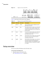
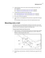
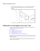
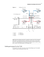
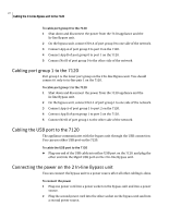
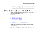
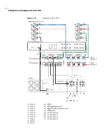
20 Cabling the 2 In-line Bypass unit to the 7120 3 Using the screws supplied with your rack, securely attach the L-brackets to the posts on both sides of the bypass unit, as shown in the following diagram. Cabling the 2 In-line Bypass unit to the 7120 You must connect the USB port, and you can connect one or both port groups from the 2 In-line Bypass unit to the 7120. See the sections: ■ Cabling port group 0 to the 7120 ■ Cabling port group 1 to the 7120 ■ Cabling the USB port to the 7120 ■ Connecting the power on the 2 In-line Bypass unit Warning: To prevent a possible electric shock, do not connect the power until all other cabling is done. Figure 1-7 shows the USB port connection and both port group connections to the proper ports on the 7120.
-
 1
1 -
2
-
3
-
4
-
5
-
6
-
7
-
8
-
9
-
10
-
11
-
12
-
13
-
14
-
 15
15 -
 16
16 -
 17
17 -
 18
18 -
 19
19 -
 20
20 -
 21
21 -
 22
22 -
 23
23 -
 24
24 -
 25
25 -
26
-
27
-
28
-
29
-
30
 |
 |
