Toshiba Satellite Pro A210-EZ2201 Maintenance Manual - Page 184
Installing the CPU Cooling Module and Fan for VGA card Model
 |
View all Toshiba Satellite Pro A210-EZ2201 manuals
Add to My Manuals
Save this manual to your list of manuals |
Page 184 highlights
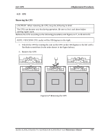
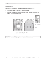
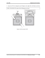
4 Replacement Procedures 4.14 CPU Cooling Module Installing the CPU Cooling Module and Fan (for VGA card Model) Install the cooling Module according to the following procedures and Figures 4-23, 4-24. CAUTION: When installing the cooling module, keep the following in mind: 1. Be sure to confirm the correct position for the module. 2. Secures the relevant screws on the main board according to the number sequence sealed on heat sink module. NOTE: Apply silicon grease with a special syringe to cover the surface of the CPU chip completely. 1. If silicon grease is already applied to the CPU and fan module, wipe them off with a cloth. By using a special syringe, apply silicon grease G7762 to the CPU chip center so that the entire CPU chip is covered with the grease G7762. 2. Install the CPU cooling module into the correct position in the computer. 3. Place the CPU cooling module and bracket in the correct position and secure them with two M2x4 black flat-head screws. 4-44 Satellite A210/A215/Satellite Pro A210/EQUIUM A210/SATEGO A210 Maintenance Manual
-
 1
1 -
2
-
3
-
4
-
5
-
6
-
7
-
8
-
9
-
10
-
11
-
12
-
13
-
14
-
15
-
16
-
17
-
18
-
19
-
20
-
21
-
22
-
23
-
24
-
25
-
26
-
27
-
28
-
29
-
30
-
31
-
32
-
33
-
34
-
35
-
36
-
37
-
38
-
39
-
40
-
41
-
42
-
43
-
44
-
45
-
46
-
47
-
48
-
49
-
50
-
51
-
52
-
53
-
54
-
55
-
56
-
57
-
58
-
59
-
60
-
61
-
62
-
63
-
64
-
65
-
66
-
67
-
68
-
69
-
70
-
71
-
72
-
73
-
74
-
75
-
76
-
77
-
78
-
79
-
80
-
81
-
82
-
83
-
84
-
85
-
86
-
87
-
88
-
89
-
90
-
91
-
92
-
93
-
94
-
95
-
96
-
97
-
98
-
99
-
100
-
101
-
102
-
103
-
104
-
105
-
106
-
107
-
108
-
109
-
110
-
111
-
112
-
113
-
114
-
115
-
116
-
117
-
118
-
119
-
120
-
121
-
122
-
123
-
124
-
125
-
126
-
127
-
128
-
129
-
130
-
131
-
132
-
133
-
134
-
135
-
136
-
137
-
138
-
139
-
140
-
141
-
142
-
143
-
144
-
145
-
146
-
147
-
148
-
149
-
150
-
151
-
152
-
153
-
154
-
155
-
156
-
157
-
158
-
159
-
160
-
161
-
162
-
163
-
164
-
165
-
166
-
167
-
168
-
169
-
170
-
171
-
172
-
173
-
174
-
175
-
176
-
177
-
178
-
 179
179 -
 180
180 -
 181
181 -
 182
182 -
 183
183 -
 184
184 -
 185
185 -
 186
186 -
 187
187 -
 188
188 -
 189
189 -
190
-
191
-
192
-
193
-
194
-
195
-
196
-
197
-
198
-
199
-
200
-
201
-
202
-
203
-
204
-
205
-
206
-
207
-
208
-
209
-
210
-
211
-
212
-
213
-
214
-
215
-
216
-
217
-
218
-
219
-
220
-
221
-
222
-
223
-
224
-
225
-
226
-
227
-
228
-
229
-
230
-
231
-
232
-
233
-
234
-
235
-
236
-
237
-
238
-
239
-
240
-
241
-
242
-
243
-
244
-
245
-
246
-
247
-
248
-
249
-
250
-
251
-
252
-
253
-
254
-
255
-
256
 |
 |
