Toshiba Satellite Pro A210-EZ2201 Maintenance Manual - Page 196
Installing the 15.4-inch LCD Module
 |
View all Toshiba Satellite Pro A210-EZ2201 manuals
Add to My Manuals
Save this manual to your list of manuals |
Page 196 highlights
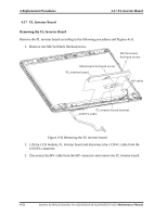
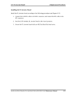
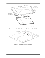
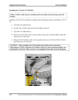
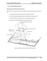
4 Replacement Procedures 4.18 LCD Module Installing the 15.4-inch LCD Module NOTE: LCD/FL cable must be carefully peeled away before disconnecting it from the module. Install the 15.4-inch LCD module according to the following procedures and Figures 4-32, 433. 1. Turn the LCD upside down. 2. Connect the LCD/FL cable to the LCD module connector. 3. Turn the LCD right side up. 4. Place the LCD bracket in the correct position and secure it with two M2x3 white flat head screws on each side. 5. Please the LCD module in the correct position and secure it with two M2.5x4 black flat heat screws on each side. CAUTION: When installing the LCD module, please follow below instruction: When plug in LCD/FL cable into LCD module connector, need to plug horizontally. For Sharp panel, if LCD/FL cable connector is not plugged horizontally, it may be damaged. 4-56 Satellite A210/A215/Satellite Pro A210/EQUIUM A210/SATEGO A210 Maintenance Manual
-
 1
1 -
2
-
3
-
4
-
5
-
6
-
7
-
8
-
9
-
10
-
11
-
12
-
13
-
14
-
15
-
16
-
17
-
18
-
19
-
20
-
21
-
22
-
23
-
24
-
25
-
26
-
27
-
28
-
29
-
30
-
31
-
32
-
33
-
34
-
35
-
36
-
37
-
38
-
39
-
40
-
41
-
42
-
43
-
44
-
45
-
46
-
47
-
48
-
49
-
50
-
51
-
52
-
53
-
54
-
55
-
56
-
57
-
58
-
59
-
60
-
61
-
62
-
63
-
64
-
65
-
66
-
67
-
68
-
69
-
70
-
71
-
72
-
73
-
74
-
75
-
76
-
77
-
78
-
79
-
80
-
81
-
82
-
83
-
84
-
85
-
86
-
87
-
88
-
89
-
90
-
91
-
92
-
93
-
94
-
95
-
96
-
97
-
98
-
99
-
100
-
101
-
102
-
103
-
104
-
105
-
106
-
107
-
108
-
109
-
110
-
111
-
112
-
113
-
114
-
115
-
116
-
117
-
118
-
119
-
120
-
121
-
122
-
123
-
124
-
125
-
126
-
127
-
128
-
129
-
130
-
131
-
132
-
133
-
134
-
135
-
136
-
137
-
138
-
139
-
140
-
141
-
142
-
143
-
144
-
145
-
146
-
147
-
148
-
149
-
150
-
151
-
152
-
153
-
154
-
155
-
156
-
157
-
158
-
159
-
160
-
161
-
162
-
163
-
164
-
165
-
166
-
167
-
168
-
169
-
170
-
171
-
172
-
173
-
174
-
175
-
176
-
177
-
178
-
179
-
180
-
181
-
182
-
183
-
184
-
185
-
186
-
187
-
188
-
189
-
190
-
 191
191 -
 192
192 -
 193
193 -
 194
194 -
 195
195 -
 196
196 -
 197
197 -
 198
198 -
 199
199 -
 200
200 -
 201
201 -
202
-
203
-
204
-
205
-
206
-
207
-
208
-
209
-
210
-
211
-
212
-
213
-
214
-
215
-
216
-
217
-
218
-
219
-
220
-
221
-
222
-
223
-
224
-
225
-
226
-
227
-
228
-
229
-
230
-
231
-
232
-
233
-
234
-
235
-
236
-
237
-
238
-
239
-
240
-
241
-
242
-
243
-
244
-
245
-
246
-
247
-
248
-
249
-
250
-
251
-
252
-
253
-
254
-
255
-
256
 |
 |
