Toshiba Satellite Pro A210-EZ2201 Maintenance Manual - Page 199
Touch Pad and Button Board, Replacement Procedure
 |
View all Toshiba Satellite Pro A210-EZ2201 manuals
Add to My Manuals
Save this manual to your list of manuals |
Page 199 highlights
4.20 Touch Pad and Button Board 4 Replacement Procedures 4.20 Touch Pad and Button Board Removing the Touch Pad and Button Board Remove the touch pad and button board according to the following procedures and Figure 435. 1. Disconnect the touch pad flat cables from JP1 on the touch pad. 2. Disconnect the button board flat cable from CN2000 on the button board. 3. Remove six M2.5x4 white flat head screws securing the touch pad. 4. Remove the touch pad bracket, button board and touch pad. M2.5x4 whit flat head screw Button board SUMI-card Button board CN2000 Touch pad bracket Touch pad JP1 Figure 4-35 Removing the touch pad and button board Satellite A210/A215/Satellite Pro A210/EQUIUM A210/SATEGO A210 Maintenance Manual 4-59
-
 1
1 -
2
-
3
-
4
-
5
-
6
-
7
-
8
-
9
-
10
-
11
-
12
-
13
-
14
-
15
-
16
-
17
-
18
-
19
-
20
-
21
-
22
-
23
-
24
-
25
-
26
-
27
-
28
-
29
-
30
-
31
-
32
-
33
-
34
-
35
-
36
-
37
-
38
-
39
-
40
-
41
-
42
-
43
-
44
-
45
-
46
-
47
-
48
-
49
-
50
-
51
-
52
-
53
-
54
-
55
-
56
-
57
-
58
-
59
-
60
-
61
-
62
-
63
-
64
-
65
-
66
-
67
-
68
-
69
-
70
-
71
-
72
-
73
-
74
-
75
-
76
-
77
-
78
-
79
-
80
-
81
-
82
-
83
-
84
-
85
-
86
-
87
-
88
-
89
-
90
-
91
-
92
-
93
-
94
-
95
-
96
-
97
-
98
-
99
-
100
-
101
-
102
-
103
-
104
-
105
-
106
-
107
-
108
-
109
-
110
-
111
-
112
-
113
-
114
-
115
-
116
-
117
-
118
-
119
-
120
-
121
-
122
-
123
-
124
-
125
-
126
-
127
-
128
-
129
-
130
-
131
-
132
-
133
-
134
-
135
-
136
-
137
-
138
-
139
-
140
-
141
-
142
-
143
-
144
-
145
-
146
-
147
-
148
-
149
-
150
-
151
-
152
-
153
-
154
-
155
-
156
-
157
-
158
-
159
-
160
-
161
-
162
-
163
-
164
-
165
-
166
-
167
-
168
-
169
-
170
-
171
-
172
-
173
-
174
-
175
-
176
-
177
-
178
-
179
-
180
-
181
-
182
-
183
-
184
-
185
-
186
-
187
-
188
-
189
-
190
-
191
-
192
-
193
-
 194
194 -
 195
195 -
 196
196 -
 197
197 -
 198
198 -
 199
199 -
 200
200 -
 201
201 -
 202
202 -
 203
203 -
 204
204 -
205
-
206
-
207
-
208
-
209
-
210
-
211
-
212
-
213
-
214
-
215
-
216
-
217
-
218
-
219
-
220
-
221
-
222
-
223
-
224
-
225
-
226
-
227
-
228
-
229
-
230
-
231
-
232
-
233
-
234
-
235
-
236
-
237
-
238
-
239
-
240
-
241
-
242
-
243
-
244
-
245
-
246
-
247
-
248
-
249
-
250
-
251
-
252
-
253
-
254
-
255
-
256
 |
 |

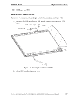
4.20 Touch Pad and Button Board
4 Replacement Procedure
s
4.20
Touch Pad and Button Board
Removing the Touch Pad and Button Board
Remove the touch pad and button board according to the following procedures and Figure 4-
35.
1.
Disconnect the touch pad flat cables from JP1 on the touch pad.
2.
Disconnect the button board flat cable from CN2000 on the button board.
3.
Remove six M2.5x4 white flat head screws securing the touch pad.
4.
Remove the touch pad bracket, button board and touch pad.
M2 5x4 whit flat head screw
.
Touch pad
Touch pad bracket
Button board
SUMI card
-
Button board
CN2000
JP1
Figure 4-35 Removing the touch pad and button board
Satellite A210/A215/Satellite Pro A210/EQUIUM A210/SATEGO A210
Maintenance Manual
4
-
59