Toshiba Satellite Pro A210-EZ2201 Maintenance Manual - Page 193
FL Inverter Board, Replacement Procedures
 |
View all Toshiba Satellite Pro A210-EZ2201 manuals
Add to My Manuals
Save this manual to your list of manuals |
Page 193 highlights
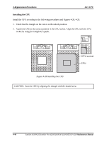
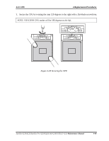
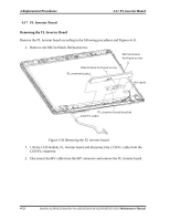
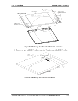
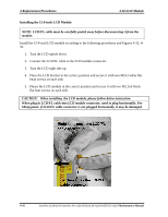
4.15 FL Inverter Board 4 Replacement Procedures Installing the FL Inverter Board Install the FL inverter board according to the following procedures and Figures 4-31. 1. Connect the LCD/FL cable to LCD/FL connector, and connect the HV cable to the HV connector. 2. Seat the LCD module, FL inverter board in the correct position. 3. Secure the FL inverter board with one M2.5x4 black flat head screw. Satellite A210/A215/Satellite Pro A210/EQUIUM A210/SATEGO A210 Maintenance Manual 4-53
-
 1
1 -
2
-
3
-
4
-
5
-
6
-
7
-
8
-
9
-
10
-
11
-
12
-
13
-
14
-
15
-
16
-
17
-
18
-
19
-
20
-
21
-
22
-
23
-
24
-
25
-
26
-
27
-
28
-
29
-
30
-
31
-
32
-
33
-
34
-
35
-
36
-
37
-
38
-
39
-
40
-
41
-
42
-
43
-
44
-
45
-
46
-
47
-
48
-
49
-
50
-
51
-
52
-
53
-
54
-
55
-
56
-
57
-
58
-
59
-
60
-
61
-
62
-
63
-
64
-
65
-
66
-
67
-
68
-
69
-
70
-
71
-
72
-
73
-
74
-
75
-
76
-
77
-
78
-
79
-
80
-
81
-
82
-
83
-
84
-
85
-
86
-
87
-
88
-
89
-
90
-
91
-
92
-
93
-
94
-
95
-
96
-
97
-
98
-
99
-
100
-
101
-
102
-
103
-
104
-
105
-
106
-
107
-
108
-
109
-
110
-
111
-
112
-
113
-
114
-
115
-
116
-
117
-
118
-
119
-
120
-
121
-
122
-
123
-
124
-
125
-
126
-
127
-
128
-
129
-
130
-
131
-
132
-
133
-
134
-
135
-
136
-
137
-
138
-
139
-
140
-
141
-
142
-
143
-
144
-
145
-
146
-
147
-
148
-
149
-
150
-
151
-
152
-
153
-
154
-
155
-
156
-
157
-
158
-
159
-
160
-
161
-
162
-
163
-
164
-
165
-
166
-
167
-
168
-
169
-
170
-
171
-
172
-
173
-
174
-
175
-
176
-
177
-
178
-
179
-
180
-
181
-
182
-
183
-
184
-
185
-
186
-
187
-
 188
188 -
 189
189 -
 190
190 -
 191
191 -
 192
192 -
 193
193 -
 194
194 -
 195
195 -
 196
196 -
 197
197 -
 198
198 -
199
-
200
-
201
-
202
-
203
-
204
-
205
-
206
-
207
-
208
-
209
-
210
-
211
-
212
-
213
-
214
-
215
-
216
-
217
-
218
-
219
-
220
-
221
-
222
-
223
-
224
-
225
-
226
-
227
-
228
-
229
-
230
-
231
-
232
-
233
-
234
-
235
-
236
-
237
-
238
-
239
-
240
-
241
-
242
-
243
-
244
-
245
-
246
-
247
-
248
-
249
-
250
-
251
-
252
-
253
-
254
-
255
-
256
 |
 |

4.15 FL Inverter Board
4 Replacement Procedures
Satellite A210/A215/Satellite Pro A210/EQUIUM A210/SATEGO A210
Maintenance Manual
4
-
53
Installing the FL Inverter Board
Install the FL inverter board according to the following procedures and Figures 4-31.
1.
Connect the LCD/FL cable to LCD/FL connector, and connect the HV cable to the
HV connector.
2.
Seat the LCD module, FL inverter board in the correct position.
3.
Secure the FL inverter board with one M2.5x4 black flat head screw.