Toshiba Satellite Pro S850 PSSESC-003001 Users Manual Canada; English - Page 40
Battery lock, Battery release latch, Memory module slot, Footnotes in Appendix C.
 |
View all Toshiba Satellite Pro S850 PSSESC-003001 manuals
Add to My Manuals
Save this manual to your list of manuals |
Page 40 highlights
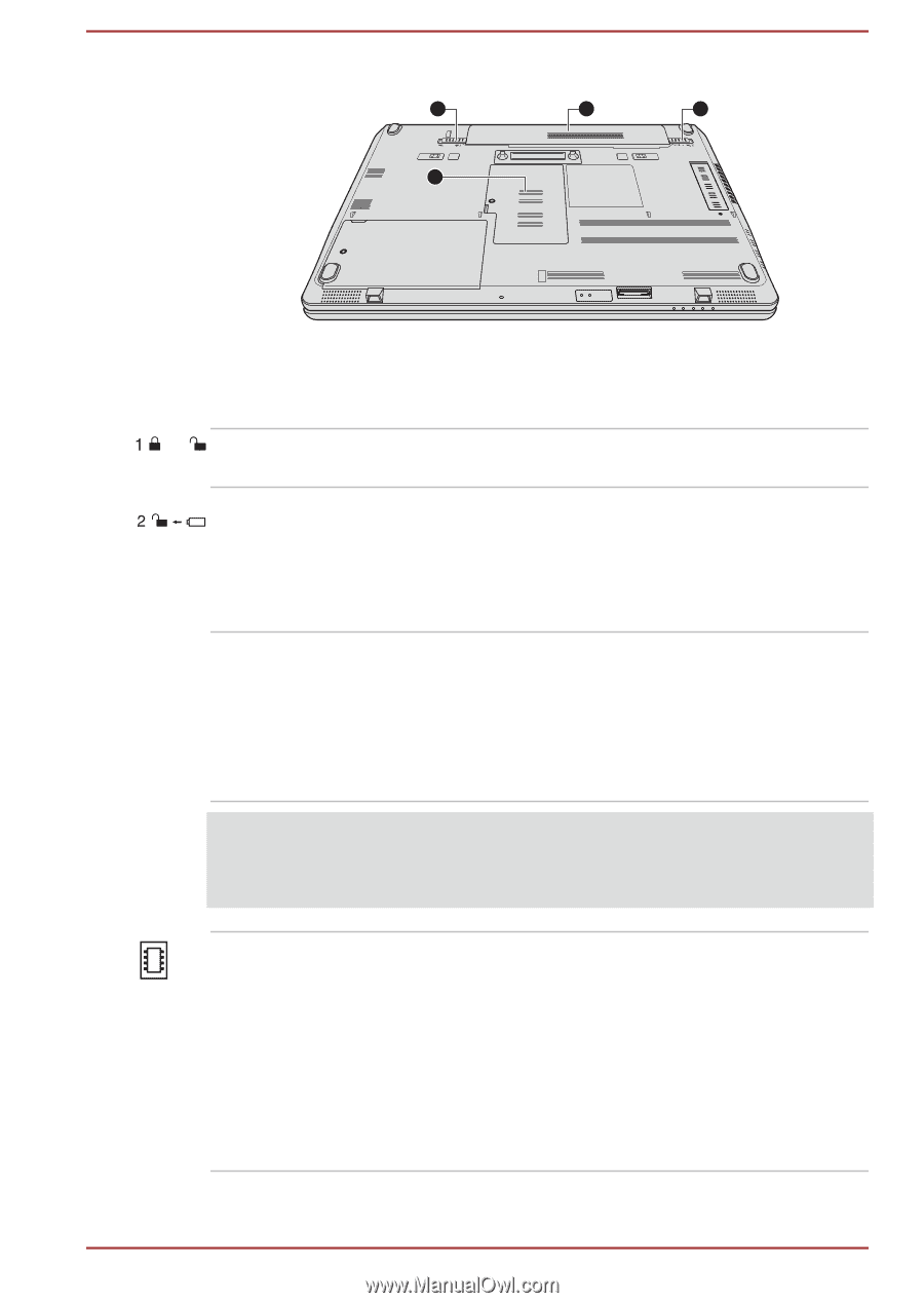
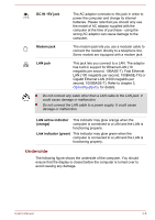
Figure 2-5 The underside of the computer 1 3 2 4 1. Battery lock 2. Battery release latch 3. Battery pack 4. Memory module slot Product appearance depends on the model you purchased. Battery lock Slide the battery lock to release the battery pack ready for removal. Battery release latch Slide and hold this latch into its "Unlock" position in order to release the battery pack for removal. For more detailed information on removing the battery pack please refer to Chapter 5, Power and Power-Up Modes. Battery pack The rechargeable lithium-ion battery pack provides power to the computer when the AC adaptor is not connected. For more detailed information on the use and operation of the battery pack please refer to Chapter 5, Power and Power-Up Modes. Legal Footnote (Battery Life) For more information regarding Battery Life, please refer to the Legal Footnotes section in Appendix C. Memory module slot The memory module slot allows the installation, replacement and removal of additional memory module. The size of the memory modules varies depending on the model. The actual amount of useable system memory may be less than the installed memory modules. Refer to the Additional memory module section in Chapter 3, Operating Basics. User's Manual 2-7
-
 1
1 -
2
-
3
-
4
-
5
-
6
-
7
-
8
-
9
-
10
-
11
-
12
-
13
-
14
-
15
-
16
-
17
-
18
-
19
-
20
-
21
-
22
-
23
-
24
-
25
-
26
-
27
-
28
-
29
-
30
-
31
-
32
-
33
-
34
-
 35
35 -
 36
36 -
 37
37 -
 38
38 -
 39
39 -
 40
40 -
 41
41 -
 42
42 -
 43
43 -
 44
44 -
 45
45 -
46
-
47
-
48
-
49
-
50
-
51
-
52
-
53
-
54
-
55
-
56
-
57
-
58
-
59
-
60
-
61
-
62
-
63
-
64
-
65
-
66
-
67
-
68
-
69
-
70
-
71
-
72
-
73
-
74
-
75
-
76
-
77
-
78
-
79
-
80
-
81
-
82
-
83
-
84
-
85
-
86
-
87
-
88
-
89
-
90
-
91
-
92
-
93
-
94
-
95
-
96
-
97
-
98
-
99
-
100
-
101
-
102
-
103
-
104
-
105
-
106
-
107
-
108
-
109
-
110
-
111
-
112
-
113
-
114
-
115
-
116
-
117
-
118
-
119
-
120
-
121
-
122
-
123
-
124
-
125
-
126
-
127
-
128
-
129
-
130
-
131
-
132
-
133
-
134
-
135
-
136
-
137
-
138
-
139
-
140
-
141
-
142
-
143
-
144
-
145
-
146
-
147
-
148
-
149
-
150
-
151
-
152
-
153
-
154
-
155
-
156
-
157
-
158
-
159
-
160
-
161
-
162
-
163
-
164
-
165
-
166
-
167
-
168
-
169
-
170
-
171
-
172
-
173
-
174
-
175
-
176
-
177
-
178
-
179
-
180
-
181
-
182
-
183
-
184
 |
 |