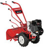
Troy-Bilt Horse Tiller Operation Manual
Troy-Bilt Horse Tiller Manual
 |
View all Troy-Bilt Horse Tiller manuals
Add to My Manuals
Save this manual to your list of manuals |
Troy-Bilt Horse Tiller manual content summary:
- Troy-Bilt Horse Tiller | Operation Manual - Page 1
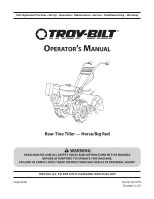
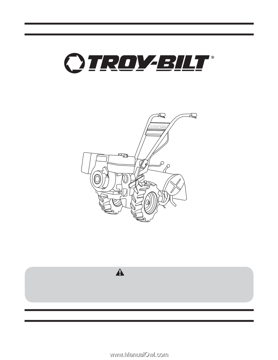
Safe Operation Practices • Set-Up • Operation • Maintenance • Service • Troubleshooting • Warranty Operator's Manual Rear-Tine Tiller - Horse/Big Red WARNING READ AND FOLLOW ALL SAFETY RULES AND INSTRUCTIONS IN THIS MANUAL BEFORE ATTEMPTING TO OPERATE THIS MACHINE. FAILURE TO COMPLY WITH THESE - Troy-Bilt Horse Tiller | Operation Manual - Page 2
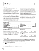
the engine manufacturer's Owner's/Operator's Manual, packed separately with your machine, for more information. Table of Contents Safe Operation Practices 3 Assembly & Set-Up 7 Controls & Features 13 Operation 14 Maintenance & Adjustments 26 Service 38 Troubleshooting 41 Replacement Parts - Troy-Bilt Horse Tiller | Operation Manual - Page 3
follow all instructions on the machine and in the manual(s) before attempting to assemble and operate. Keep this manual in a safe place for future and regular reference and for ordering replacement parts. 2. Be familiar with all controls and their proper operation. Know how to stop the machine and - Troy-Bilt Horse Tiller | Operation Manual - Page 4
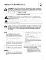
parts have stopped. Disconnect the spark plug wire and ground it against the engine to prevent unintended starting. 5. Do not change the engine governor settings or over-speed the engine. The governor controls the maximum safe operating speed of engine. 6. Maintain or replace safety and instruction - Troy-Bilt Horse Tiller | Operation Manual - Page 5
9. If the fuel tank has to be drained, do this outdoors. 10. Observe proper disposal laws and regulations for gas, oil, etc. to protect the lands. A spark arrestor for the muffler is available through your nearest engine authorized service dealer or contact the service department, P.O. Box - Troy-Bilt Horse Tiller | Operation Manual - Page 6
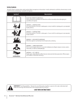
. Symbol Description READ THE OPERATOR'S MANUAL(S) Read, understand, and follow all instructions in the manual(s) before attempting to assemble and operate WARNING- ROTATING TINES Do not put hands or feet near rotating parts. Contact with the rotating parts can amputate hands and feet. WARNING - Troy-Bilt Horse Tiller | Operation Manual - Page 7
• 26 oz. Bottle SAE 30W Oil (1) • Clutch Pawl Spring (1) • Belt Adjusting Tool (1) • Plastic Cable Ties (2) • Curved Head Screw, 1⁄4-20 x 2 (1) • Flanged Lock Nut, 1⁄4-20 (1) • Pan Head Screw, #10-32 x 1⁄2 (1) • The following parts (electric start models only), packaged separately. • Nuts, 1⁄4-20 - Troy-Bilt Horse Tiller | Operation Manual - Page 8
Handlebars high enough to clear the tiller tines and pull back firmly to dislodge the tiller from the platform wheel wells. Wire Harness 1. Ground the green (and red for electric start tillers) wire(s) to the engine block. See Fig. 3-3. Figure 3-4 Connect the tiller's main harness connection to the - Troy-Bilt Horse Tiller | Operation Manual - Page 9
and the lever. Wheels/Tines/PTO Drive Lever Plates Wheel Speed Lever Forward Hole Figure 3-8 5. Retrieve the clutch pawl spring from hardware bag. Remove the temporary screw from the forward holes inserted in Step 3 and move the Wheels/Tines/PTO Lever fully forward. Install the wider hook end - Troy-Bilt Horse Tiller | Operation Manual - Page 10
instructions. assembly should appear as illustrated in Fig. 3-10. Clutch Pawl Spring Forward Hole Short Link Bar Figure 3-10 7. Test the operation of the Wheels/Tines/PTO Lever. Push the lever down until it engages in the Forward position. The clutch roller must rest beneath the adjustment - Troy-Bilt Horse Tiller | Operation Manual - Page 11
steps explain how to install and charge the battery on electric start tillers. For your safety, follow all steps and observe all accompanying safety messages. The Maintenance & Adjustments section contains other general battery maintenance and recharging instructions. WARNING! Battery produces - Troy-Bilt Horse Tiller | Operation Manual - Page 12
leading to electrical burns or an Gas & Oil Fill-Up explosion of battery gases. Never bring a gas can Service the engine with gasoline and oil as instructed in the near the positive (+) battery terminal. A short circuit Engine Operator's Manual packed separately with your tiller. could occur - Troy-Bilt Horse Tiller | Operation Manual - Page 13
tilling depth separate Engine Operator's Manual. of the tines. Wheels/Tines/PTO Drive Lever Handlebar Height Adjustment Lever Use the Wheels/Tines/PTO Drive Lever to engage and disengage The Handlebar Height Adjustment Lever is used to adjust the power to the transmission. handlebars to one - Troy-Bilt Horse Tiller | Operation Manual - Page 14
4-1 7. Attach the spark plug wire to the spark plug. 8. Check Engine Cooling System. Clear cooling fins and air intake screen of debris. See the Engine Operator's Manual. 9. Select High/Low Belt Speed range. 4. Move the Tines/PTO Clutch Lever into DISENGAGE position. NOTE: Use the ENGAGE position - Troy-Bilt Horse Tiller | Operation Manual - Page 15
a load. 4. Use the correct weight gear oil in the PTO Power transmission. 5. Warm up the transmission gear oil as follows: a. With the engine running, move the Wheel Speed Lever to FREEWHEEL (then block the wheels so they can't roll). b. Put the Tines/PTO Clutch Lever into DISENGAGE, then squeeze - Troy-Bilt Horse Tiller | Operation Manual - Page 16
Levers to use reverse. relaxed. See Fig. 4-3. 5. The tiller immediately engages in reverse. Periodically check behind you while holding the handlebars up and the Wheels/Tines/PTO Lever in its upper-most position. Stopping Reverse Motion Release the Wheels/Tines/PTO Drive Lever - the lever - Troy-Bilt Horse Tiller | Operation Manual - Page 17
tiller will buck and the engine will load down. You will know your settings are ideal when the tines break-up the soil easily, the engine does not labor, and your progress is steady and smooth. See Fig. 4-5. WHEEL SPEED AND BELT RANGE SELECTION GUIDE SLOW GEAR, LOW BELT RANGE SLOW GEAR, HIGH BELT - Troy-Bilt Horse Tiller | Operation Manual - Page 18
tiller. NOTE: Proper belt tension is important for good performance. See the Maintenance & Adjustment Section for instructions on adjusting belt tension. NOTE: If extra belt slack is needed to move the belt, just raise the Wheels/Tines/PTO Drive Lever up into REVERSE. This lowers the engine pulley - Troy-Bilt Horse Tiller | Operation Manual - Page 19
the tiller. Use your right hand to hold the Wheels/Tines/PTO Drive Lever up into REVERSE position. Use your left hand to move the belt off the top-front engine pulley groove to top-rear engine pulley groove. See Fig. 4-9. Wheels/Tines/PTO Drive Lever Top-Front Gear Clearing the Tines The tines have - Troy-Bilt Horse Tiller | Operation Manual - Page 20
three or four passes to thoroughly pulverize the soil. Figure 4-11 Figure 4-12 • If the garden size will not permit lengthwise and then crosswise tilling, then overlap the first passes by 1⁄2 a tiller width, followed by successive passes at 1⁄⁄4 width. See Fig. 4-13. 1 2 3 Figure 4-13 20 Section - Troy-Bilt Horse Tiller | Operation Manual - Page 21
Changing Speed Belts in this section for more information on changing to high range. 1 2 3 12" UNTILLED 1 REPEAT DOWNHILL Figure 4-15 • Each succeeding lower terrace is started by walking below the terrace you're preparing. For added stability of the tiller, always keep the uphill wheel in - Troy-Bilt Horse Tiller | Operation Manual - Page 22
LOW belt range and the Wheel Speed • Standing cornstalks of reasonable height can be power Gear Lever to SLOW position. As in terrace gardening, start composted. See Fig. 4-17. Pushing over (but not uprooting) at the top of the slope and overlap the first pass by half the cornstalks will often - Troy-Bilt Horse Tiller | Operation Manual - Page 23
the spark plug. 3. Place a sturdy support under the engine to prevent the engine from tipping forward when the tine attachment is removed. See Fig. 4-19. PTO Power Feature Your tiller is a self-contained PTO (Power Take-Off) Power machine that was shipped with a tine attachment installed. The tine - Troy-Bilt Horse Tiller | Operation Manual - Page 24
machine forward about one inch with Installing the Tine Attachment one hand while pulling the tine attachment back. Fig. 4-22. 1. Move the two PTO Power Unit swingout bolts outward and slide the washers up against the bolt heads. 2. Remove the support block from under the engine and slowly roll - Troy-Bilt Horse Tiller | Operation Manual - Page 25
tiller. 1. Place the Tines/PTO Clutch Lever in DISENGAGE position. 2. Move the Depth Regulator Lever down all the way into the Travel setting. 3. If using engine power, move Wheel Speed Lever to either SLOW or FAST, and use the Wheels/Tines/PTO Drive Lever to drive the wheels. 4. If the engine - Troy-Bilt Horse Tiller | Operation Manual - Page 26
Condition/Connections Check Electrical Connections Recharge Battery Check Drive Belt Tension Check Nuts and Bolts Clean Tiller Tine Shaft Lubricate Tiller Check Gear Oil Lever in Both Transmissions Check Bolo Tines for Wear Check Reverse Disc for Wear Check Air Pressure in Tire After 2-hour Before - Troy-Bilt Horse Tiller | Operation Manual - Page 27
wear to the tine shaft and its oil seals. Refer to the previous tine holder removal instructions. After cleaning away any debris and removing old grease from the tine shaft, apply fresh grease to the tine shaft. Wheel Shaft Maintenance After every 10 operating hours, remove the wheels and clear away - Troy-Bilt Horse Tiller | Operation Manual - Page 28
immediately, and replace any worn seals or gaskets. • It may be impossible to determine how much oil has been lost, so check the oil levels in the PTO transmission and the tine attachment before using the tiller again. Add any necessary gear oil. Serious damage to the transmission components can - Troy-Bilt Horse Tiller | Operation Manual - Page 29
end. First remove the dipstick from the tine attachment transmission to see which type of dipstick you have. See Fig. 6-7. Then replace the dipstick with the markings on the dipstick facing to the rear. Gear Oil Dipstick Back of Tine Shield Figure 6-7 Section 6 - Maintenance & Adjustments 29 - Troy-Bilt Horse Tiller | Operation Manual - Page 30
using the tiller. See Adding or Changing Gear Oil. For Dipsticks With Hot/Cold Markings 1. Move the tiller to level ground. 2. Pull the Depth Regulator Lever back, then push it down all the way (to engage its top notch). 3. Place a sturdy support under the engine to prevent the tiller from tilting - Troy-Bilt Horse Tiller | Operation Manual - Page 31
to contact the pulleys, drive belt or reverse disc. This can cause the belt or disc to slip on the pulleys. Figure 6-9 NOTE: If you find a plastic washer on the cover screw you removed, discard the washer. There is no need to install a replacement washer. Section 6 - Maintenance & Adjustments 31 - Troy-Bilt Horse Tiller | Operation Manual - Page 32
Lubricate the tiller as follows: 1. Oil the wheel shaft between the wheel hubs and the transmission housing. See Fig. 6-10. Wheels/Tines/PTO Drive Lever 8. Keep the PTO access area well-greased. See Fig. 6-11. If the Tines/PTO Clutch Lever becomes hard to move, squirt some oil into its access hole, - Troy-Bilt Horse Tiller | Operation Manual - Page 33
tool will fit, the belt 2. Move the Wheels/Tines/PTO Drive Lever fully down to the tension is correct. FORWARD position. The clutch roller at the bottom of the c. If the slotted part of the tool will not fit in, the belt is lever should be positioned underneath the belt adjustment too loose - Troy-Bilt Horse Tiller | Operation Manual - Page 34
These instructions explain how to inspect and adjust the various reverse drive components. But first, here's how the reverse drive system works. When you raise the Wheels/Tines/PTO Drive Lever up in REVERSE position, this lowers the rubberized reverse disc - it's attached to the engine drive pulley - Troy-Bilt Horse Tiller | Operation Manual - Page 35
bolt can be adjusted up or down Disc Edge to correct a number of reverse drive operating problems, as explained next. Checking and Adjusting the Reverse Disc 1. Verify that the linkages for Wheels/Tines/PTO Drive Lever are lubricated with oil and engine mount bars and belt adjustment block are - Troy-Bilt Horse Tiller | Operation Manual - Page 36
the engine 1. Place the Wheels/Tines/PTO Drive Lever in FORWARD recoil starter. The reverse disc should turn the lower pulley. position. See Fig. 6-21. If not, or it requires a lot of pressure to hold the lever up in REVERSE, then the reverse adjustment bolt 2. On the left side of the tiller - Troy-Bilt Horse Tiller | Operation Manual - Page 37
Move the Wheels/Tines/PTO Drive Lever to NEUTRAL. The switch body on the bottom of the engine mount tab should be resting squarely on top of the reverse adjustment bolt, and the reverse disc should be at least 3⁄16" away from the transmission drive pulley. See Fig. 6-19. If the reverse disc is any - Troy-Bilt Horse Tiller | Operation Manual - Page 38
Service 7 Belt Replacement Drive Belt 5. Lift the top half of the belt up and over the upper pulley and the rubber reverse disc, moving it in front of the reverse disc. See Fig. 7-3. 1. Move the Wheels/Tines/PTO Drive Lever to NEUTRAL position. 2. While kneeling on the right side of the tiller, - Troy-Bilt Horse Tiller | Operation Manual - Page 39
Section. 15. After installing the belt, check and adjust for correct belt tension as explained previously. Reverse Disc Follow these steps to replace the reverse disc. If your tiller has a Bumper Attachment mounted, it must be removed first. 1. Move Wheels/Tines/PTO Drive Lever in NEUTRAL position - Troy-Bilt Horse Tiller | Operation Manual - Page 40
/PTO Drive Lever to NEUTRAL, the Wheel Speed Lever to either FAST or SLOW position, and the Tines/PTO Clutch Lever to ENGAGE. 2. Gently tilt the tiller forward until the engine rests on the ground. 3. Raise the hood flap at the back of the tiller and tie it up with string. 4. Before removing a tine - Troy-Bilt Horse Tiller | Operation Manual - Page 41
change gears Tiller jumps while tilling Depth Regulator Lever difficult to move 1. Mis-adjusted drive belt and/or reverse disc 2. Loose bolt on transmission drive pulley 3. Worn worm gears 1. Loose drive belt 2. Loose bolt on transmission drive pulley 1. Tines/PTO clutch lever not engage 2. Tines - Troy-Bilt Horse Tiller | Operation Manual - Page 42
V-Belt 742-04223 742-04224 Bolo Tine (LH), 12" Bolo Tine (RH), 12" 934-04231 Wheel, 16 x 4.6 x 8 756-04171 Reverse Disc 1909286P Throttle Cable Phone (800) 800-7310 to order replacement parts or a complete Parts Manual (have your full model number and serial number ready). Parts Manual - Troy-Bilt Horse Tiller | Operation Manual - Page 43
Notes 10 43 - Troy-Bilt Horse Tiller | Operation Manual - Page 44
other peril or natural disaster. Damage resulting from the installation or use of any part, accessory or attachment not approved by Troy-Bilt for use with the product(s) covered by this manual will void your warranty as to any resulting damage. Belts are warranted to be free from defects in material
-
 1
1 -
 2
2 -
 3
3 -
 4
4 -
 5
5 -
 6
6 -
 7
7 -
8
-
9
-
10
-
11
-
12
-
13
-
14
-
15
-
16
-
17
-
18
-
19
-
20
-
21
-
22
-
23
-
24
-
25
-
26
-
27
-
28
-
29
-
30
-
31
-
32
-
33
-
34
-
35
-
36
-
37
-
38
-
39
-
40
-
41
-
42
-
43
-
44
 |
 |
TROY-BILT LLC, P.O. BOX 361131 CLEVELAND, OHIO 44136-0019
Printed In USA
O
PERATOR
’
S
M
ANUAL
Safe Operation Practices • Set-Up • Operation •
Maintenance • Service • Troubleshooting •
Warranty
WARNING
READ AND FOLLOW ALL SAFETY RULES AND INSTRUCTIONS IN THIS MANUAL
BEFORE ATTEMPTING TO OPERATE THIS MACHINE.
FAILURE TO COMPLY WITH THESE INSTRUCTIONS MAY RESULT IN PERSONAL INJURY.
Rear-Tine Tiller — Horse/Big Red
Form No. 769-07754
(December 13, 2011