Troy-Bilt Horse Tiller Operation Manual - Page 35
Checking and Adjusting the Reverse Drive System - problems
 |
View all Troy-Bilt Horse Tiller manuals
Add to My Manuals
Save this manual to your list of manuals |
Page 35 highlights
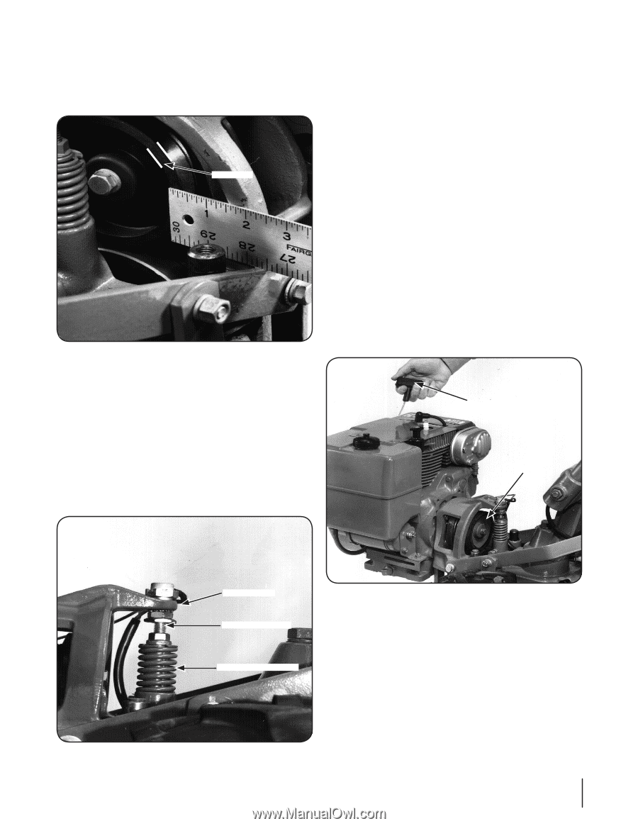
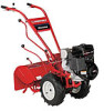
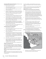
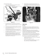
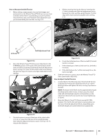
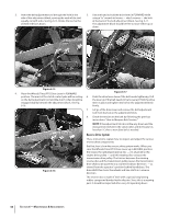
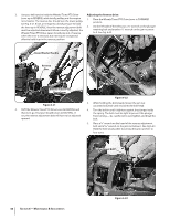
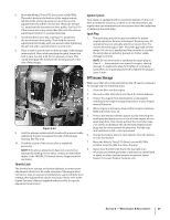
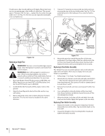
1. Measure the width of the outside edge of the disc as shown This action compresses the reverse spring and plunger assembly, in Fig. 6-18. Replace the disc before the rubber edge wears requiring you to hold the lever up in REVERSE. When you release to a thickness of 1⁄8" or less. Failure to do so could cause the the lever, the spring automatically pushes the lever back into steel underneath the rubber to damage the transmission NEUTRAL position. pulley. The spring and plunger assembly is designed to prevent the reverse disc from making contact with the transmission pulley until you shift into REVERSE. When the lever is in NEUTRAL, the switch body on the bottom of the engine mount tab should be resting squarely on top of the reverse adjustment bolt. See Fig. 6-19. The reverse adjustment bolt can be adjusted up or down Disc Edge to correct a number of reverse drive operating problems, as explained next. Checking and Adjusting the Reverse Disc 1. Verify that the linkages for Wheels/Tines/PTO Drive Lever are lubricated with oil and engine mount bars and belt adjustment block are lubricated with grease. See Lubrication earlier in this section. Figure 6-18 2. Place Wheels/Tines/PTO Drive Lever in NEUTRAL. Briefly pull out the engine recoil starter handle while watching the reverse disc. The disc should turn, but lower pulley should not. See Fig. 6-20. If the reverse disc turns the lower pulley, or if it is located closer than 3⁄16" to the pulley, reverse adjustment bolt should be adjusted upward. Moving the adjustment bolt upward will also solve the problem of a tiller that goes into REVERSE on its own. 2. Look for big cracks or missing chunks of rubber from the disc. If so damaged, the disc should be replaced immediately. See the Service section of this manual for instructions on replacing the disc. NOTE: Extend the life of the reverse disc by always pausing in NEUTRAL before shifting between FORWARD and REVERSE. Also, the reverse disc is not suited for continuous or sustained reverse operation. Use reverse sparingly. Checking and Adjusting the Reverse Drive System When the Wheels/Tines/PTO Drive Lever is moved up into REVERSE, the engine and engine mount move down to press on the reverse adjustment bolt. See Fig. 6-19. Recoil Starter Handle Reverse Disc Switch Body Adjustment Bolt Spring and Plunger Figure 6-19 Figure 6-20 Section 6 - Maintenance & Adjustments 35
-
 1
1 -
2
-
3
-
4
-
5
-
6
-
7
-
8
-
9
-
10
-
11
-
12
-
13
-
14
-
15
-
16
-
17
-
18
-
19
-
20
-
21
-
22
-
23
-
24
-
25
-
26
-
27
-
28
-
29
-
 30
30 -
 31
31 -
 32
32 -
 33
33 -
 34
34 -
 35
35 -
 36
36 -
 37
37 -
 38
38 -
 39
39 -
 40
40 -
41
-
42
-
43
-
44
 |
 |