Vizio VP505XVT User Manual - Page 10
Rear Panel Connections - purchase
 |
View all Vizio VP505XVT manuals
Add to My Manuals
Save this manual to your list of manuals |
Page 10 highlights
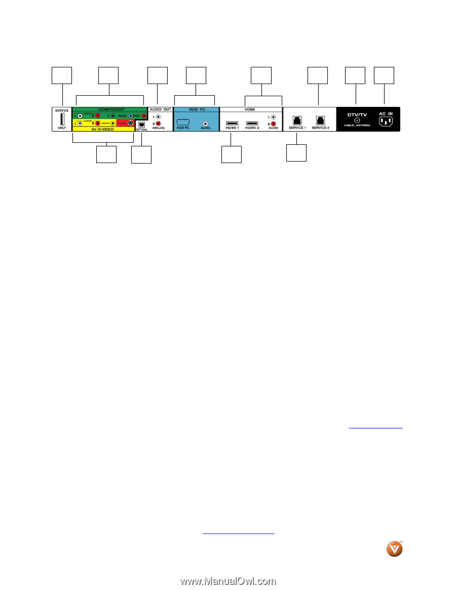
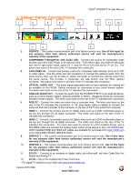
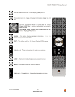
1.3 Rear Panel Connections 1 2 5 6 8 VIZIO® VP505XVT1A User Manual 10 11 12 3 4 7 9 1. SERVICE - This custom communication port is for factory service only. Use of this input for any purpose other than factory authorized service will void the manufacturer's warranty of this equipment. 2. COMPONENT (YPb/CbPr/Cr with Audio L/R) - Connect the source for component video devices such as a DVD Player or set top box here. From left to right, use white for left audio and red for right audio inputs, green for Y, blue for Pb (or Cb) and red for Pr (or Cr). The green color band on the rear of the TV indicates this connection. 3. AV/S-VIDEO IN - Connect the primary source for composite video devices, such as a VCR or video game. Use the white and red connectors to connect the external audio from the same source, then use the S-Video or yellow connector to connect the external video from the same source. The S-Video, if connected, will take priority over AV RCA (yellow) connector. The yellow color band on the rear of the TV indicates this connection. 4. OPTICAL AUDIO OUT - The audio signal associated with an input selected for viewing will be available on this SPDIF Optical connector for connection to your home theatre system. The white color band on the rear of the TV indicates this connection. 5. ANALOG AUDIO OUT - Connect the audio from the PLASMA FHDTV to an external device, such as a home theater system, external amplifier or stereo. Speakers cannot be connected directly to these outputs. The white color band on the rear of the TV indicates this connection. 6. RGB PC - Connect the video and audio from a computer here. The blue color band on the rear of the TV indicates this connection. A 1/8" plug stereo cable is needed to connect the audio out from the computer to the connector in the rear of the TV for audio from computer. 7. HDMI 1 - Connect the primary source for digital video such as a DVD multimedia player or set top box through this all digital connector. The white color band on the rear of the TV indicates this connection. 8. HDMI 2 - Connect a secondary source for digital video such as a DVD multimedia player or set top box through this all digital connector. The white color band on the rear of the TV indicates this connection. For users who want to connect to a DVI enabled device, use a DVI-HDMI cable and connect the Analog Audio output of the device to the L+R AUDIO here. VIZIO Certified HDMI and HDMI-DVI cables are available for purchase from www.VIZIO.com or by calling 888-VIZIOCE (888-849-4623). 9. SERVICE 1 - This custom communication port is for factory service only. Use of this input for any purpose other than factory authorized service will void the manufacturer's warranty of this equipment. 10. SERVICE 2 - This custom communication port is for factory service only. Use of this input for any purpose other than factory authorized service will void the manufacturer's warranty of this equipment. 11. DTV/TV - Connect to an antenna or digital cable (out-of-the-wall, not from Cable Box) for Digital and Analog TV.* 12. AC IN - Plug in the supplied AC Power Cord here. * For digital TV stations in your area visit www.antennaweb.org. Version 8/21/2008 10 www.VIZIO.com
-
 1
1 -
2
-
3
-
4
-
 5
5 -
 6
6 -
 7
7 -
 8
8 -
 9
9 -
 10
10 -
 11
11 -
 12
12 -
 13
13 -
 14
14 -
 15
15 -
16
-
17
-
18
-
19
-
20
-
21
-
22
-
23
-
24
-
25
-
26
-
27
-
28
-
29
-
30
-
31
-
32
-
33
-
34
-
35
-
36
-
37
-
38
-
39
-
40
-
41
-
42
-
43
-
44
-
45
-
46
-
47
-
48
-
49
-
50
-
51
-
52
-
53
-
54
-
55
-
56
-
57
-
58
-
59
-
60
-
61
-
62
-
63
-
64
-
65
-
66
-
67
-
68
-
69
-
70
-
71
-
72
-
73
-
74
-
75
-
76
-
77
-
78
-
79
-
80
-
81
-
82
-
83
-
84
-
85
-
86
-
87
-
88
-
89
-
90
-
91
-
92
-
93
 |
 |