Weider 9000 Uk Manual - Page 11
Attach the Pulley, a Cable Trap 26,
 |
View all Weider 9000 manuals
Add to My Manuals
Save this manual to your list of manuals |
Page 11 highlights
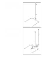
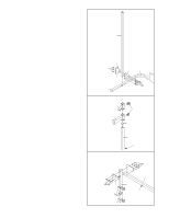
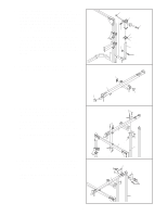
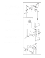
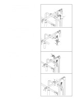
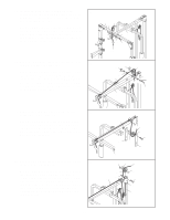
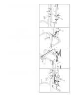
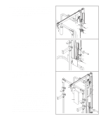
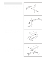
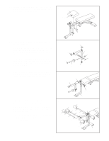
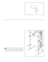
18. Identify the High Cable (31), which is the 18 shorter of the two remaining cables. Route the eyelet end of the Cable up through the indicated hole in the Top Frame (8). Wrap the High Cable (31) around a 90mm Pulley (24). Attach the Pulley inside of the Top Frame (8) with an M10 x 65mm Bolt (54), two 15mm x 13mm Spacers (39), two M10 Washers (52), and an M10 Nylon Locknut (49). 19. Route the High Cable (31) down through the indi- 19 cated hole in the Top Frame (8). Wrap the High Cable (31) around a 90mm Pulley (24). Attach the Pulley and a Cable Trap (26) inside of the Top Frame (8) with an M10 x 65mm Bolt (54), a 15mm x 13mm Spacer (39), a 15mm x 10mm Spacer (40), two M10 Washers (52), and an M10 Nylon Locknut (49). 49 24 52 39 52 8 39 54 31 49 26 52 40 31 8 24 39 52 54 20. Remove the 90mm Pulleys (24) from the pre- 20 assembled Pulley Plates (28). Wrap the High Cable (31) under a 90mm Pulley (24). Attach the Pulley and a Cable Trap (26) to the second hole from the top of the two Pulley Plates (28) with an M10 x 45mm Bolt (57) and an M10 Nylon Locknut (49). 21. Route the High Cable (31) up through the indicat- 21 ed hole in the Top Frame (8). Wrap the High Cable (31) around a 90mm Pulley (24). Attach the Pulley, a Cable Trap (26), a 15mm x 8mm Spacer (55), and a 15mm x 10mm Spacer (40) to the Top Frame (8) with an M10 x 68mm Bolt (46), the two attached Support Plates (14), and an M10 Nylon Locknut (49). Do not overtighten the Bolt; the pulley must be able to pivot easily. 49 28 26 31 24 57 28 55 26 31 24 40 49 8 46 14 6 11
-
 1
1 -
2
-
3
-
4
-
5
-
 6
6 -
 7
7 -
 8
8 -
 9
9 -
 10
10 -
 11
11 -
 12
12 -
 13
13 -
 14
14 -
 15
15 -
 16
16 -
17
-
18
-
19
-
20
-
21
-
22
-
23
-
24
-
25
-
26
-
27
-
28
 |
 |
